Liquids dispensing systems and methods

a liquid dispensing system and liquid technology, applied in the direction of positive displacement liquid engines, liquid fuel engines, instruments, etc., can solve the problems of destroying the dispense liquid, affecting the quality of the product, so as to minimize or prevent the formation of bubbles in the dispense liquid, prevent the pressure from falling, and minimize the effect of bubble formation

Active Publication Date: 2010-02-02
PALL CORP
View PDF19 Cites 21 Cited by
  • Summary
  • Abstract
  • Description
  • Claims
  • Application Information

AI Technical Summary

Benefits of technology

[0010]Embodiments of the invention may include one or more of these aspects of the invention. Embodiments which supply dispense liquid to the suction inlet of a pump to prevent the pressure from falling below a predetermined value are highly advantageous. For example, by preventing the pressure from falling below a predetermined value, the formation of bubbles in the dispense liquid is minimized or prevented entirely. Preferably, embodiments of the present invention drive the dispense liquid to the suction inlet of a pump at a sufficient pressure or flow rate to prevent the pressure at the suction inlet of the pump from falling below the predetermined value when the dispense liquid is drawn into the pump. Embodiments which minimize or prevent formation of bubbles in the dispense liquid maintain the high purity of the dispense liquid, thereby improving the integrity and reliability of any process using the dispense liquid.

Problems solved by technology

At such a microscopic level, the introduction or formation of impurities in the dispense liquid is a major problem.
Particulate contamination is a highly problematic impurity.
Contamination of the dispense liquid with even the smallest of particles can ruin not only the dispense liquid, which can be extremely expensive, but also the products in an entire production run.
Bubbles in the dispense liquid is another problematic impurity.
The formation of bubbles in the dispense liquid can be equally as devastating as particulate contamination.
Another major problem associated with dispense liquids is their sensitive, fragile nature; they are easily damaged.
High pressures and high flow rates can adversely alter or change the properties of a dispense liquid, negatively affecting not only the dispense liquid but also the products made with the dispense liquid.

Method used


Image

  • Liquids dispensing systems and methods
  • Liquids dispensing systems and methods
  • Liquids dispensing systems and methods

Examples


example

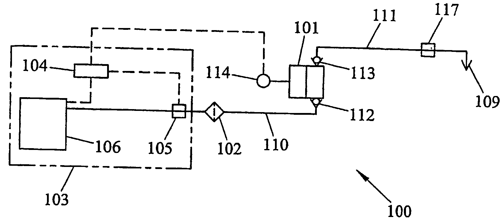
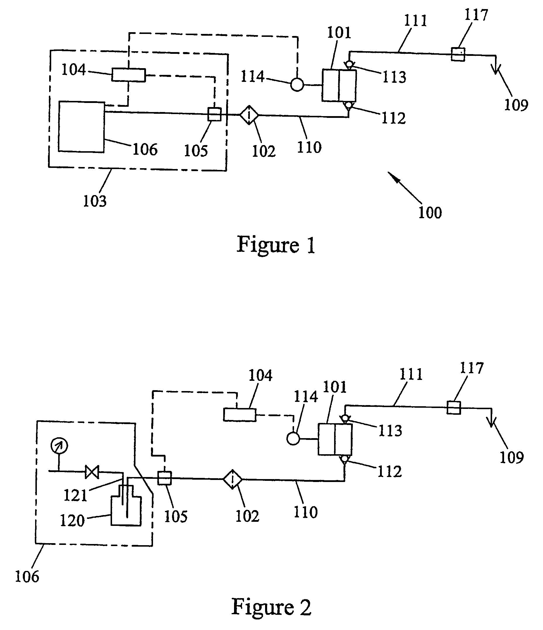
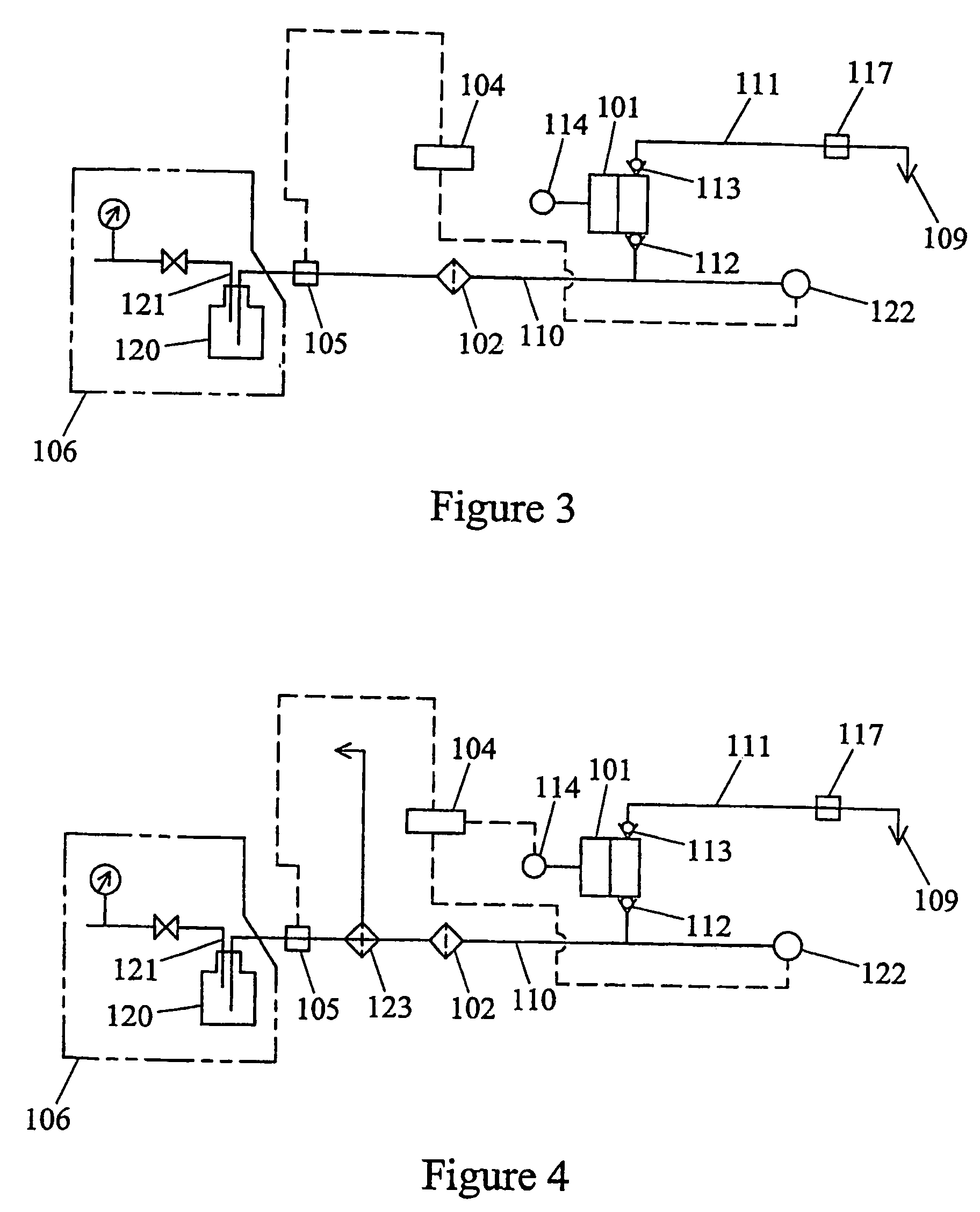
[0069]The test system shown in FIG. 12 dispenses isobutyl alcohol. The test system comprises a feed assembly 106 which includes a bag 141 of isobutyl alcohol in a pressure canister 140, such as the arrangement available from ATMI Packaging under the trade designation NOWPAK. The isobutyl alcohol has a viscosity of 4 mPa s at 20° C. The pressure canister is pressurized to 9.8 kpa by a nitrogen feed 121 and the isobutyl alcohol is discharged from the feed assembly 106 via a feed line 110. A filter 102 having a 0.05 micron rating, a pressure sensor 122 and an air-operated valve 105 are respectively positioned between the feed assembly 106 and the suction inlet 112 of a dispense pump 101. A controller 104 is coupled to the motor 114 of the dispense pump 101 and to the valve 105 in the feed line 110. The dispense outlet 113 of the dispense pump 101 fluidly communicates with a dispense point 109 via a dispense line 111 and an air operated valve 117 in the dispense line 111. A container 11...


PUM


Abstract

A liquid dispensing system (100) supplies a dispense liquid using a pump (101), wherein the system minimizes contamination of, and bubble formation in, the dispense liquid. The pressure at the suction side of the pump may be limited to a predetermined value.

Description

[0001]This application claims the benefit of priority of U.S. Provisional Application No. 60 / 354,301 filed on Feb. 7, 2002, which provisional application is incorporated by reference.TECHNICAL FIELD[0002]The present invention relates to arrangements, systems, and methods for dispensing liquids. More particularly, the invention relates to arrangements, systems, and methods for dispensing high purity liquids.BACKGROUND OF THE INVENTION[0003]In many industries, it is highly desirable to precisely dispense a very sensitive, high purity liquid in the course of manufacturing a product. For example, dispense liquids are commonly used in the microelectronics industry, such as the liquid crystal industry, the semiconductor industry, and the ink-jet printing industry, in the process of manufacturing a variety of products. An example of such a dispense liquid is a photoresist, which may be used in procedures such as photo lithography to produce an integrated circuit.[0004]In these industries, ...

Claims


Application Information

Patent Timeline
Patent Type & Authority Patents(United States)
IPC IPC(8): B67D1/00F04B23/02B01J4/00B67D1/10B67D1/12B67D7/76F04B53/16
CPCB67D1/10B67D1/12B67D1/1231B67D1/1243B67D7/76B67D2210/0001
Inventor HIRANAGA, HAJIMETSUZUKI, SHUICHIHOSHINO, TATSUYA
Owner PALL CORP
Why Eureka
Try Eureka