Electrophotographic photosensitive member, process cartridge, and electrophotographic apparatus

a photosensitive member and electrophotography technology, applied in the direction of electrographic process, electrographic discharge, instruments, etc., can solve the problems of inability to reduce the contact area between the photosensitive member surface and the elastic charge member or cleaning blade, and the effect of suppressing friction memory cannot be obtained

Inactive Publication Date: 2010-02-02
CANON KK
View PDF17 Cites 45 Cited by
  • Summary
  • Abstract
  • Description
  • Claims
  • Application Information

AI Technical Summary

Benefits of technology

[0013]As a result of intensive investigations, the present inventors discovered that the above-described problems could be effectively improved upon by having in the surface of an electrophotographic photosensitive member specific depressed portions and a specific hole transporting material, thereby arriving at the present invention.
[0017]The electrophotographic photosensitive member of the present invention can provide an electrophotographic photosensitive member in which friction memory does not easily occur, and a process cartridge and an electrophotographic apparatus which have the electrophotographic photosensitive member.

Problems solved by technology

However, even when the electrophotographic photosensitive members described in Japanese Patent Applications Laid-Open No.
Further, when the electrophotographic photosensitive member described in Japanese Patent Application Laid-Open No. 2001-066814 which had been slightly modified is used, for a photosensitive member with shallow depressed portions, the contact area between the photosensitive member surface and the elastic charge member or cleaning blade cannot be reduced.
As a result, the effects of suppressing friction memory may not be obtained.

Method used


Image

  • Electrophotographic photosensitive member, process cartridge, and electrophotographic apparatus
  • Electrophotographic photosensitive member, process cartridge, and electrophotographic apparatus
  • Electrophotographic photosensitive member, process cartridge, and electrophotographic apparatus

Examples


example 1

[0146]An aluminum cylinder 30 mm in diameter and 260.5 mm in length which had been subjected to surface cutting processing was used as a support (cylindrical support).

[0147]Next, a solution containing the following components was dispersed for about 20 hours with a ball mill to prepare a conductive layer coating solution.

[0148]

Powder containing barium sulfate particles60 partshaving a coating layer of tin oxide (trade name:“Pastran PC1”; manufactured by Mitsui Mining& Smelting Co., Ltd.)Titanium oxide (trade name: “Titanix JR”;15 partsmanufactured by Tayca Corporation)Resol type phenolic resin (trade name:43 parts“Phenolite J-325”; manufactured by DICCorporation Co., Ltd.; solid content: 70%)Silicone oil (trade name: “SH28PA”;0.015 parts  manufactured by Toray-Dow Corning Silicone Co., Ltd.)Silicone resin (trade name: “Tospearl 120”;3.6 parts manufactured by Toshiba Silicone Co., Ltd.)2-Methoxy-1-propanol50 partsMethanol50 parts

[0149]The thus-prepared conductive layer coating soluti...

example 2

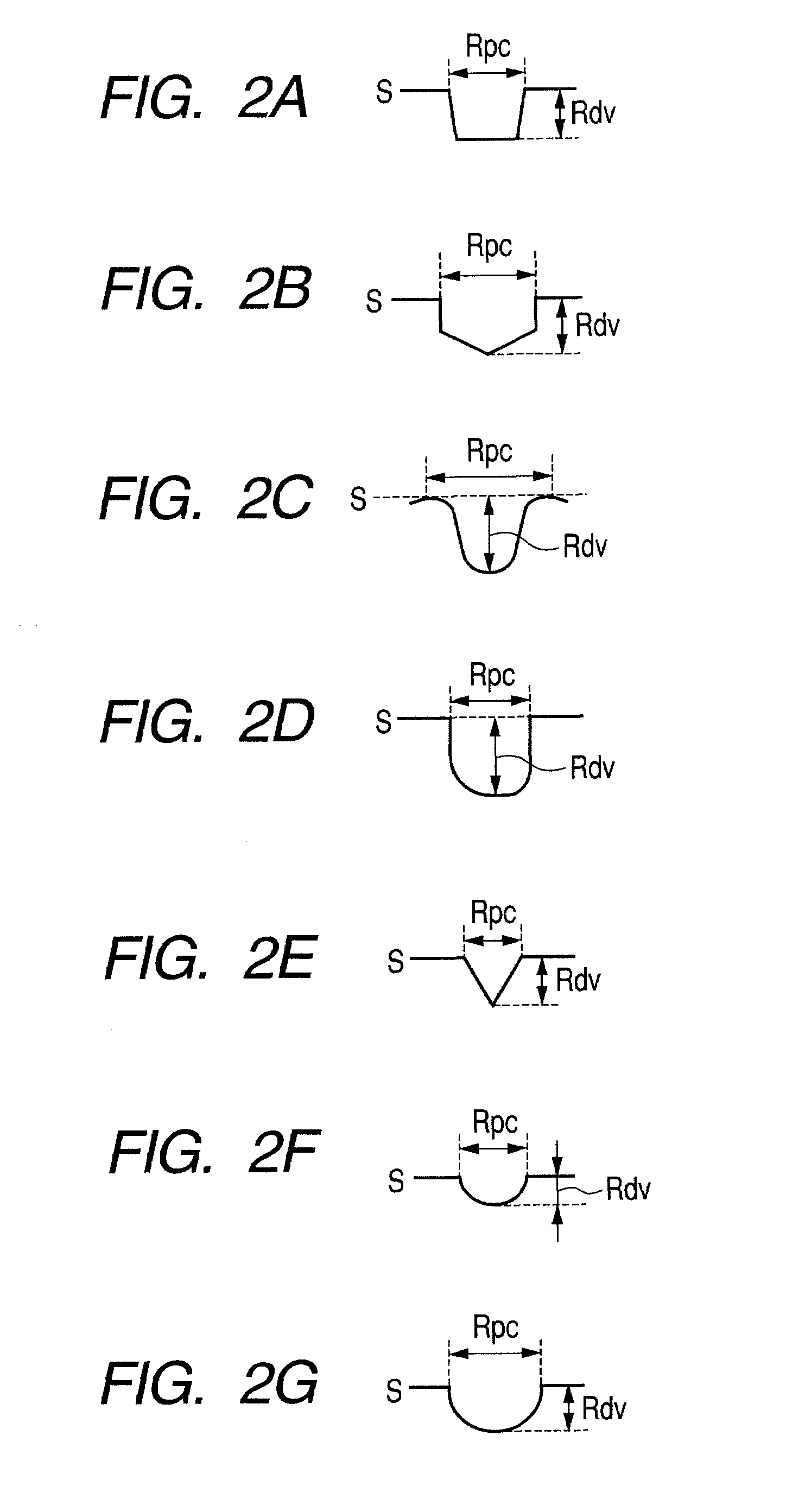
[0168]An electrophotographic photosensitive member was produced in the same manner as in Example 1. Next, the surface of the electrophotographic photosensitive member was subjected to the same processing as in Example 1, except that, in the mold used for Example 1, the minor axis diameter indicated by D in FIG. 10 was changed from 1.0 μm to 0.5 μm, the interval indicated by E in FIG. 10 was changed from 1.0 μm to 0.5 μm, and the height indicated by F in FIG. 10 was changed from 0.8 μm to 0.4 μm. It was confirmed by measuring the surface profile in the same manner as in Example 1 that conical depressed portions were formed. The measurement results are shown in Table 1. Further, the depressed portions were formed at 0.5 μm intervals, and the area ratio was calculated to be 20%. The properties of the electrophotographic photosensitive member were evaluated in the same manner as in Example 1. The results are shown in Table 1.

example 3

[0169]An electrophotographic photosensitive member was produced in the same manner as in Example 1. Next, the surface of the electrophotographic photosensitive member was subjected to the same processing as in Example 1, except that, in the mold used for Example 1, the minor axis diameter indicated by D in FIG. 10 was changed from 1.0 μm to 0.2 μm, the interval indicated by E in FIG. 10 was changed from 1.0 μm to 0.2 μm, and the height indicated by F in FIG. 10 was changed from 0.8 μm to 0.16 μm. It was confirmed by measuring the surface profile in the same manner as in Example 1 that conical depressed portions were formed. The measurement results are shown in Table 1. Further, the depressed portions were formed at 0.2 μm intervals, and the area ratio was calculated to be 20%. The properties of the electrophotographic photosensitive member were evaluated in the same manner as in Example 1. The results are shown in Table 1.


PUM

PropertyMeasurementUnit
ionization potentialaaaaaaaaaa
depth Rdvaaaaaaaaaa

Abstract

Provided is an electrophotographic photosensitive member in which friction memory does not easily occur, and a process cartridge and an electrophotographic apparatus which have the electrophotographic photosensitive member. The electrophotographic photosensitive member having a photosensitive layer has a surface layer having a plurality of depressed portions which are independent from one another, where the minor axis diameter of the depressed portions is Rpc and the depth indicating the distance between the innermost part of a depressed portion and the opening surface thereof is Rdv, the depressed portions have a ratio of depth to minor axis diameter (Rdv / Rpc) on a surface of the photosensitive member of 1.0 or less, and the photosensitive layer has a charge transporting material with an ionization potential of 4.5 eV or more and 5.3 eV or less.

Description

[0001]This application is a continuation of International Application No. PCT / JP2008 / 055611, filed on Mar. 18, 2008, which claims the benefit of Japanese Patent Application No. 2007-080967 filed on Mar. 27, 2007.BACKGROUND OF THE INVENTION[0002]1. Field of the Invention[0003]The present invention relates to an electrophotographic photosensitive member, and a process cartridge and an electrophotographic apparatus which have the electrophotographic photosensitive member.[0004]2. Description of the Related Art[0005]Due to advantages such as low price and high productivity, electrophotographic photosensitive members providing a photosensitive layer (organic photosensitive layer) which uses an organic material as a photoconductive material (a charge generating material and a charge transporting material), a so-called “organic electrophotographic photosensitive member”, on a support are becoming more widespread as an electrophotographic photosensitive member. Due to advantages such as hig...

Claims


Application Information

Patent Timeline
Patent Type & Authority Patents(United States)
IPC IPC(8): G03G15/00
CPCG03G5/047G03G5/0525G03G5/0542G03G5/144G03G5/0696G03G5/102G03G5/0564G03G5/06G03G5/147
Inventor KITAMURA, WATARUHIRANO, HIDETOSHIOKUDA, ATSUSHIOGAKI, HARUNOBU
Owner CANON KK
Why Eureka
Try Eureka