Dual-injection locked frequency dividing circuit

a frequency dividing circuit and locking technology, applied in the direction of oscillator generators, pulse techniques, counting chain pulse counters, etc., can solve the problems of narrow frequency locking range, insufficient use in broadband applications, unsatisfactory and inadequate, etc., and achieve the effect of wide frequency locking range and low power consumption

Inactive Publication Date: 2010-02-02
NAT TAIWAN UNIV
View PDF12 Cites 125 Cited by
  • Summary
  • Abstract
  • Description
  • Claims
  • Application Information

AI Technical Summary

Benefits of technology

[0014]The dual-injection locked frequency dividing circuit according to the invention is characterized by the provision of a dual-injection interface module on the input end for dividing the input signal into two parts for use as two injection signals, wherein the first injection signal is rendered in the form of a voltage signal and injected through a direct injection manner to the internal oscillation circuitry, while the second injection signal is rendered in the form of an electrical current and injected through a resonant circuit to the internal oscillation circuitry. This feature allow the proposed frequency dividing circuit to have broad frequency locking range and low power consumption.

Problems solved by technology

However, in practice, one drawback to the ILFD circuit architecture is that it can only offer a narrow frequency locking range which would be unsatisfactory and inadequate for use in broadband applications.
However, still one drawback of this technology is that its frequency locking range is only 3.2 GHz, which is still unsatisfactory and inadequate for use in such broadband applications.

Method used


Image

  • Dual-injection locked frequency dividing circuit
  • Dual-injection locked frequency dividing circuit
  • Dual-injection locked frequency dividing circuit

Examples


Embodiment Construction

[0025]The dual-injection locked frequency dividing circuit according to the invention is disclosed in full details by way of preferred embodiments in the following with reference to the accompanying drawings.

Application and Function of the Invention

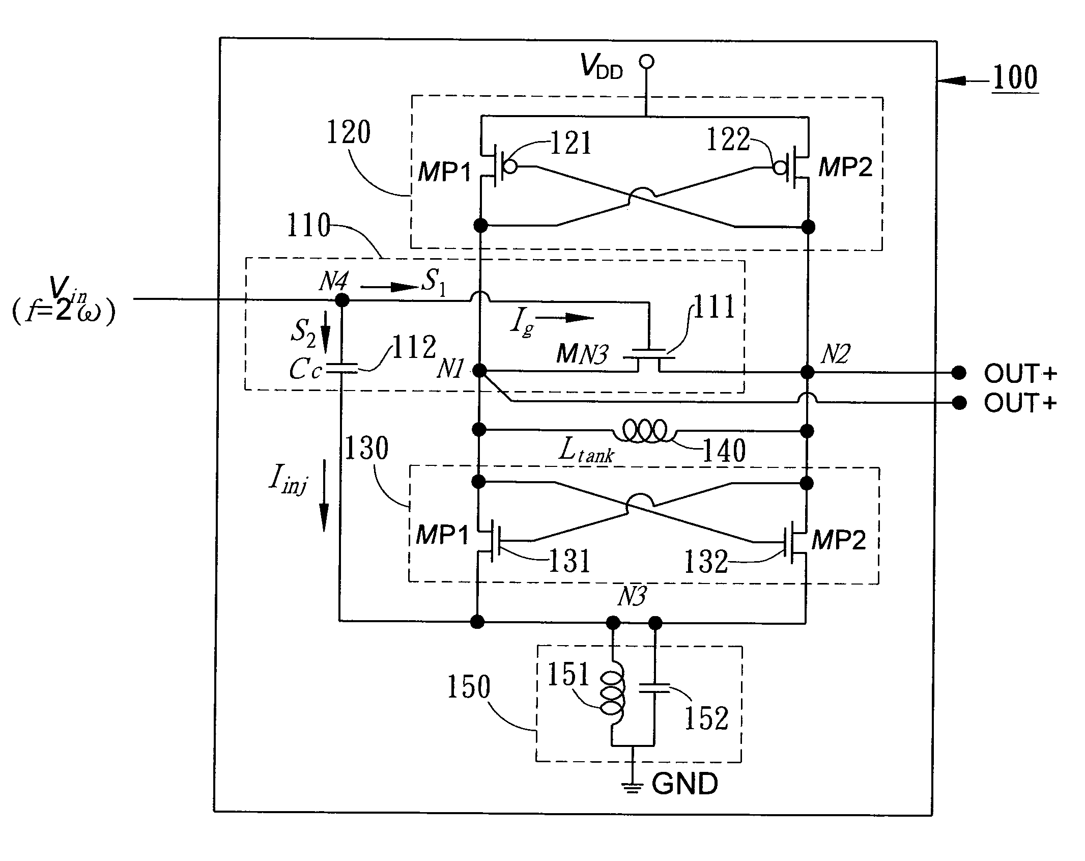
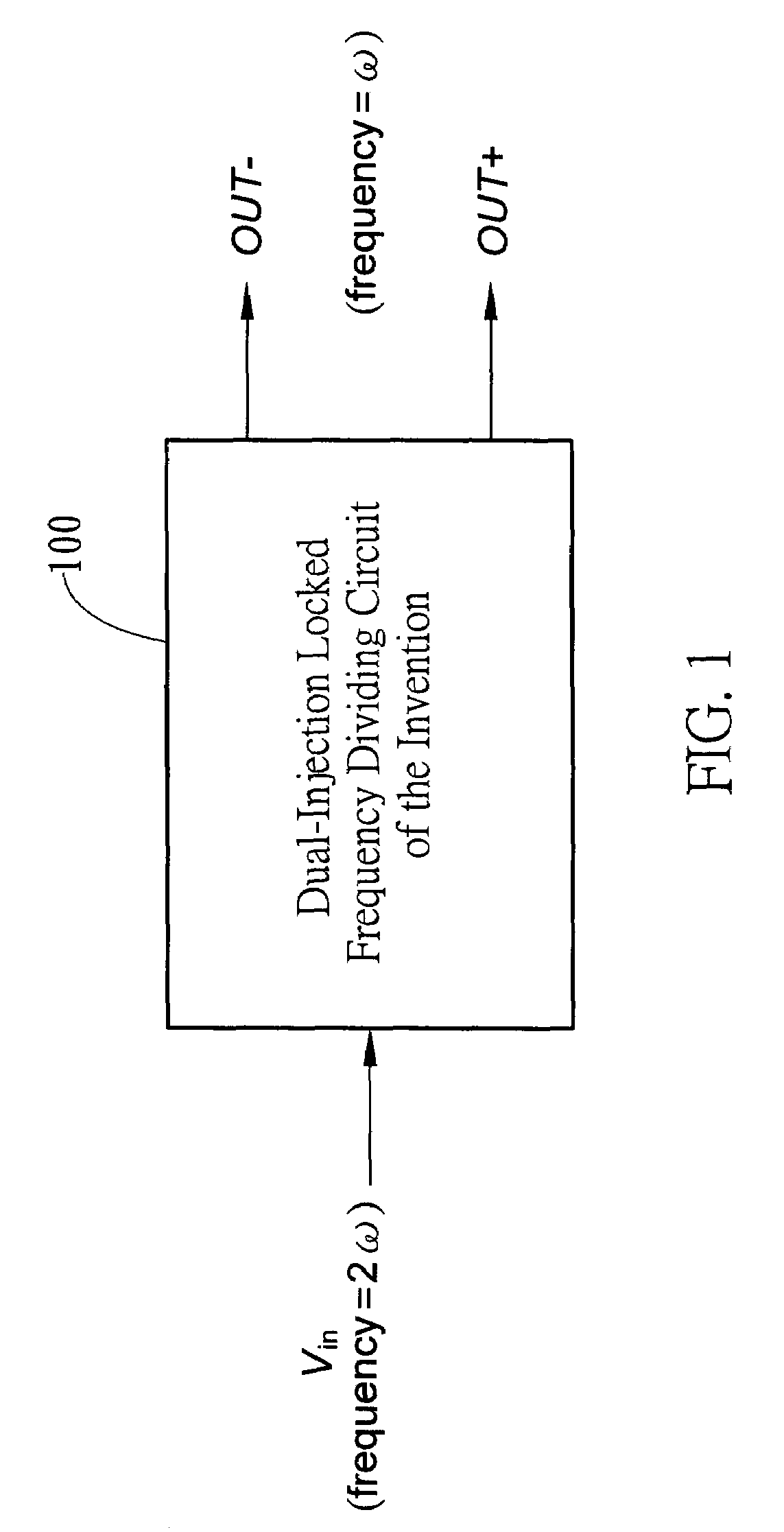
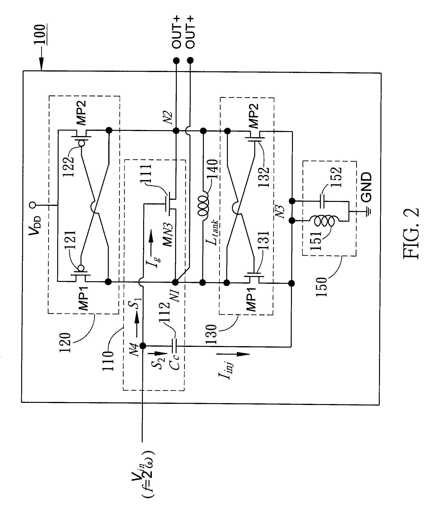
[0026]FIG. 1 is a schematic diagram showing the input / output (I / O) functional model of the dual-injection locked frequency dividing circuit according to the invention (which is here encapsulated in a box indicated by the reference numeral 100, and is hereinafter referred in short as “frequency dividing circuit”). As shown, the frequency dividing circuit of the invention 100 is designed with an I / O interface having a signal input port Vin and a pair of differential signal output ports including a positive differential output port (OUT+) and a negative differential output port (OUT−). The signal input port Vin is used to receive an input signal (whose frequency is represented by 2ω in FIG. 1).

[0027]In operation, the frequency dividing circu...


PUM


Abstract

A dual-injection locked frequency dividing circuit is proposed, which is designed for integration to a gigahertz signal processing circuit system for providing a frequency dividing function to gigahertz signals. The proposed circuit architecture is characterized by the provision of a dual-injection interface module on the input end for dividing the input signal into two parts for use as two injection signals, wherein the first injection signal is rendered in the form of a voltage signal and injected through a direct injection manner to the internal oscillation circuitry, while the second injection signal is rendered in the form of an electrical current and injected through a resonant circuit to the internal oscillation circuitry. This feature allow the proposed frequency dividing circuit to have broad frequency locking range and low power consumption.

Description

BACKGROUND OF THE INVENTION[0001]1. Field of the Invention[0002]This invention relates to a dual-injection locked frequency dividing circuit which is designed for use with a gigahertz signal processing system, particularly of the type that operates in the frequency range from 35.7 GHz to 54.9 GHz (gigahertz), for providing a frequency dividing function to gigahertz signals.[0003]2. Description of Related Art[0004]With the advent of wireless digital communication technologies, such as wireless networking, mobile phones, GPS (Global Positioning System), and digital TV, the design and manufacture of high-speed digital circuit boards that operate with signals within the gigahertz range is in high demand in the electronics industry. Nowadays, the operating frequency of high-speed digital circuitry has advanced to the ranges of RF (radio frequency), microwave, and millimeter waves.[0005]In the design of high-speed digital circuitry, frequency dividers are an important component that can c...

Claims


Application Information

Patent Timeline
Patent Type & Authority Patents(United States)
IPC IPC(8): H03K21/00
CPCH03K21/08
Inventor CHEN, YI-JAN EMERYLUO, TANG-NIAN
Owner NAT TAIWAN UNIV
Why Eureka
Try Eureka