Systems and methods for protecting a sensitive device from corrosion

a sensitive device and corrosion protection technology, applied in the field of data storage systems, can solve the problems of increasing the spacing between the magnetically active portion of the sensor and the magnetic coating on the tape, affecting the performance of the tape, so as to reduce the relative humidity and reduce the effect of eliminating the corrosion of the sensor

Active Publication Date: 2010-02-02
INT BUSINESS MASCH CORP
View PDF6 Cites 117 Cited by
  • Summary
  • Abstract
  • Description
  • Claims
  • Application Information

AI Technical Summary

Benefits of technology

[0010]A method for protecting a magnetic head according to one embodiment includes reducing a relative humidity in a vicinity of a magnetic head by passing an elevated bias current through a sensor of the head during at least some time periods when the sensor is not in use for reading data, the elevated bias current being chosen to be sufficient to heat the sensor to a level which will reduce the local relative humidity to below a threshold level for reducing or eliminating corrosion of the sensor.
[0011]A method for protecting a magnetic head according to another embodiment includes, during a reading operation, setting potentials of a sensor and a substrate of the sensor to about a common value; and during an idle period, raising the potential of the substrate to a level above that of the sensor.
[0012]A method for protecting a magnetic head according to yet another embodiment includes detecting a relative humidity in a vicinity of a magnetic head; comparing the detected relative humidity to a threshold level; and if the detected relative humidity is above the threshold level, passing an elevated bias current through a sensor of the head during at least some time periods when the sensor is not in use for reading data, the elevated bias current being chosen to be sufficient to heat the sensor to a level which will reduce the local relative humidity to below the threshold level for reducing or eliminating corrosion of the sensor.

Problems solved by technology

However, the development of small footprint, higher performance tape drive systems has created various problems in the design of a tape head assembly for use in such systems.
The Wallace spacing is, among other factors, due to asperities on the tape and to erosion of the sensor due to wear.
Build up of non-magnetic material between the sensor and the tape magnetic coating can also cause Wallace spacing.
Corrosion or oxidation initiated at the TBS of the sensor or the protective poles surrounding the sensor can also lead to Wallace spacing losses.
Corrosion or oxidation of the sensor at the TBS can result in surface oxidation of the sensor metals which result in an increase in the spacing between the magnetically active portion of the sensor and the magnetic coating on the tape.
High level corrosion can completely destroy the magnetic response of the sensor.
However, such materials are in contact with the tape, and tend to wear away, thereby leaving the sensor unprotected.
The methods of depositing the hard protective coatings require large expensive tools which preclude the reapplication of a hard coating once it has been worn off.
Further, such recession results in Wallace spacing signal losses, which are exacerbated the higher the density of the recorded data on the media.
For tape heads, sensors can be recessed and flux guided, but flux guides have not worked well due to head processing difficulty and to spacing loss.
Alternatively, GMR heads may be fabricated using materials that have improved corrosion resistance, but these materials may not provide optimal magnetic performance (amplitude in particular).
Head-media stiction is usually addressed by making the media rougher, but this may adversely affect the signal-to-noise ratio and thus detection capability and ultimately areal density.

Method used


Image

  • Systems and methods for protecting a sensitive device from corrosion
  • Systems and methods for protecting a sensitive device from corrosion
  • Systems and methods for protecting a sensitive device from corrosion

Examples


Embodiment Construction

[0041]The following description is made for the purpose of illustrating the general principles of the present invention and is not meant to limit the inventive concepts claimed herein. Further, particular features described herein can be used in combination with other described features in each of the various possible combinations and permutations.

[0042]Unless otherwise specifically defined herein, all terms are to be given their broadest possible interpretation including meanings implied from the specification as well as meanings understood by those skilled in the art and / or as defined in dictionaries, treatises, etc.

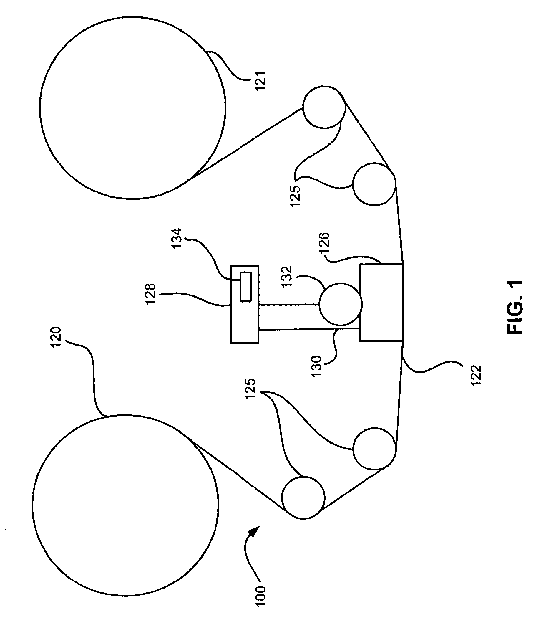
[0043]The following description discloses several preferred embodiments of tape-based storage systems, as well as operation and / or component parts thereof.

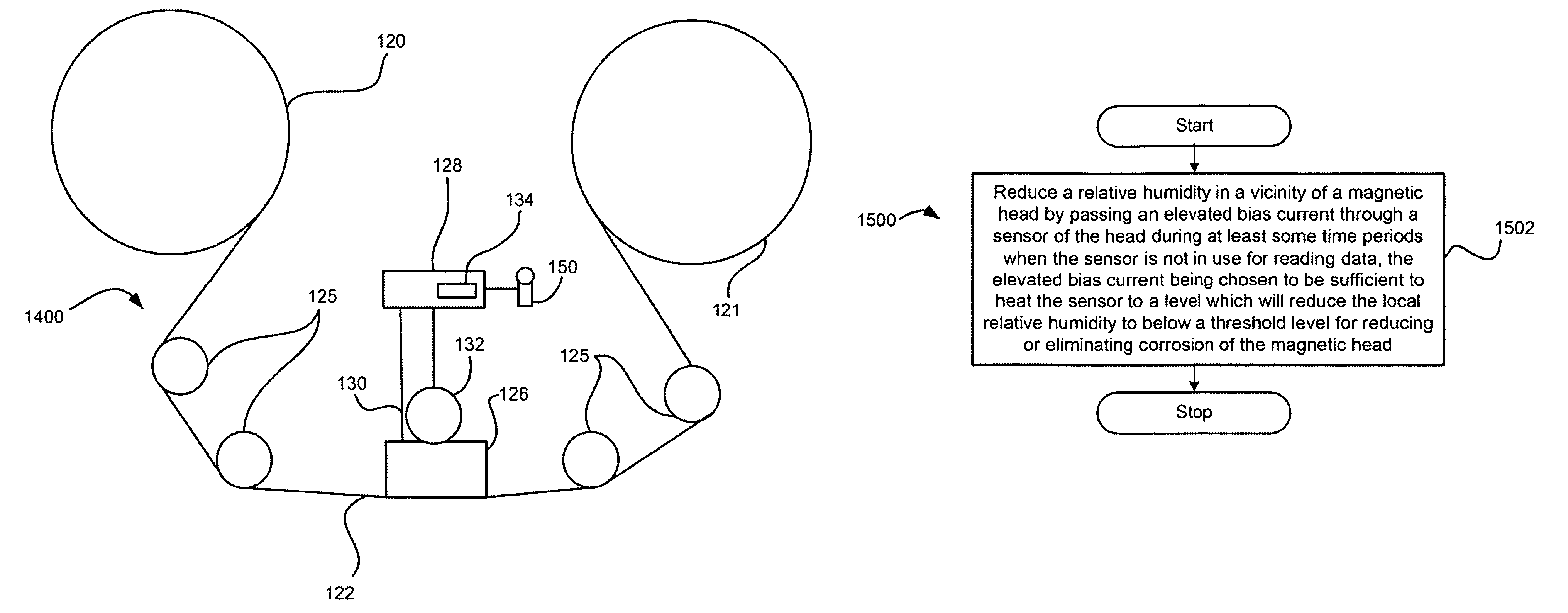
[0044]In one general embodiment, a method for protecting a magnetic head comprises applying an organic coating to a magnetic head for reducing exposure of the head to oxidation promoting materials, and storing the ma...


PUM

PropertyMeasurementUnit
RHaaaaaaaaaa
RHaaaaaaaaaa
temperatureaaaaaaaaaa

Abstract

A method for protecting a magnetic head according to one embodiment includes reducing a relative humidity in a vicinity of a magnetic head by passing an elevated bias current through a sensor of the head during at least some time periods when the sensor is not in use for reading data, the elevated bias current being chosen to be sufficient to heat the sensor to a level which will reduce the local relative humidity to below a threshold level for reducing or eliminating corrosion of the sensor. Additional methods are also presented.

Description

RELATED APPLICATIONS[0001]This application is a continuation in part of U.S. patent application Ser. No. 12 / 115,449, filed May 5, 2008, and which is herein incorporated by reference.FIELD OF THE INVENTION[0002]The present invention relates to data storage systems, and more particularly, this invention relates to magnetic heads for tape drives, and coatings to prevent corrosion thereon.BACKGROUND OF THE INVENTION[0003]In magnetic storage systems, data is read from and written onto magnetic recording media utilizing magnetic transducers commonly. Data is written on the magnetic recording media by moving a magnetic recording transducer to a position over the media where the data is to be stored. The magnetic recording transducer then generates a magnetic field, which encodes the data into the magnetic media. Data is read from the media by similarly positioning the magnetic read transducer and then sensing the magnetic field of the magnetic media Read and write operations may be indepen...

Claims


Application Information

Patent Timeline
Patent Type & Authority Patents(United States)
IPC IPC(8): G11B5/03G11B33/14
CPCG11B5/3106G11B5/40G11B5/41
Inventor IBEN, ICKO E. TIMMCKINLEY, WAYNE ALANRANDALL, LEE CURTIS
Owner INT BUSINESS MASCH CORP
Why Eureka
Try Eureka