Controller

a controller and controller technology, applied in the field of controllers, can solve the problems of inability to perform precision machining, inability to implement high-quality implementation, and vibrations in the driven body, and achieve the effects of eliminating time loss, suppressing vibrations of the driven body, and increasing operation accuracy such as machining accuracy

Inactive Publication Date: 2010-02-02
FANUC LTD
View PDF11 Cites 22 Cited by
  • Summary
  • Abstract
  • Description
  • Claims
  • Application Information

AI Technical Summary

Benefits of technology

[0018]Furthermore, the change means may reduce a speed command to the driven body, instead of decreasing the variation ratio of a speed command to the driven body.
[0021]Furthermore, the change means may decrease a speed command to the driven body, instead of decreasing the variation ratio of a speed command to the driven body.
[0024]In accordance with the present invention, the stoppage of vibrations of the driven body is detected based on the detected value of acceleration detected with acceleration detection means after the positioning command is completed and the next operation of cutting or tool replacement is then started. Therefore, the waiting time to the start of the next operation of cutting or tool replacement after the positioning command is completed is a necessary and sufficient time, time loss is eliminated, and operation accuracy such as machining accuracy can be increased. Furthermore, changing the command speed or changing the variation ratio of the speed command so as to inhibit the vibrations of the driven body occurring as the speed changes during acceleration or deceleration makes it possible to suppress the vibrations of the driven body and to conduct more stable operation control.

Problems solved by technology

Machining position, speed and machining torque are controlled by such feedback control of position, speed, and current, but when the speed and acceleration of the driven body change rapidly, vibrations sometime occur in the driven body due to such rapid changes.
In particular, when positioning of the driven body to the machining position in working machinery is conducted by rapid feed, vibrations occur due to a rapid change in speed when the driven body is stopped, and if the machining operation such as cutting is started immediately after the positioning, the driven body (work, table, tool) is subjected to the next operation such as machining in a vibrating state, the next operation cannot be implemented with high accuracy, and if the next operation is cutting, then precision machining cannot be conducted.
Furthermore, when the next operation after the positioning operation is a tool replacement operation, then the tool replacement cannot be implemented correctly if the driven body was caused to vibrate in the positioning operation.
With the conventional method, in which when the next operation after the positioning operation of the driven body, such as fast feed, is a machining operation such as cutting or a tool replacement operation, a transition to the next operation of cutting or tool replacement is made after the vibrations calmed down and a stable state was assumed, the waiting time is difficult to set.
If a long waiting time is set, the entire machining time increases.
Conversely, if a short waiting time is set, the next operation of cutting or tool replacement is started, while the driven body (work, table, tool, etc.) still vibrates, and the desired machining accuracy or correct tool replacement cannot be attained.
The optimum waiting time is, therefore, difficult to set.
When the speed is changed rapidly in the course of machining operation such as cutting, there is a risk of vibrations occurring in the driven body and decreasing the machining accuracy.

Method used


Image

  • Controller
  • Controller
  • Controller

Examples


Embodiment Construction

[0032]The present invention will be explained below based on the examples of application thereof to a numerical controller as a controller of a machine tool.

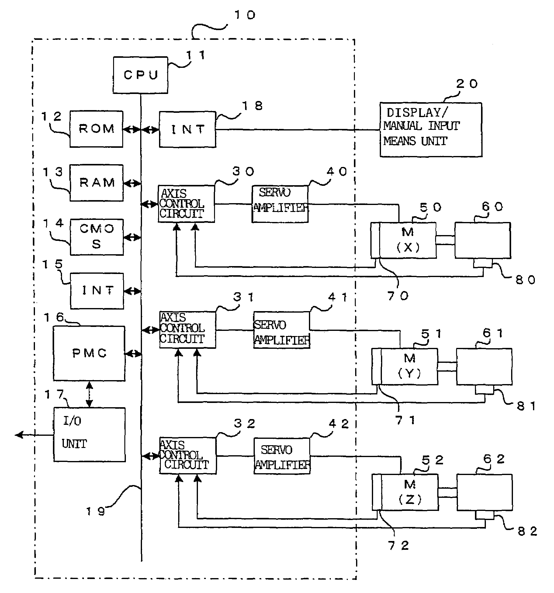
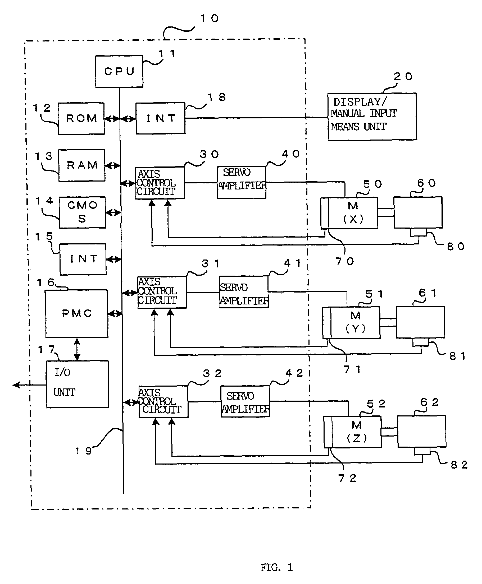
[0033]FIG. 1 is a block diagram of the main portion of the controller in accordance with the present invention. A CPU 11 is a processor for controlling the entire controller 10 executing numerical control. The CPU 11 reads a system program stored in a ROM 12 via a bus 19 and controls the entire controller according to this system program. A RAM 13 stores temporary computational data, display data, and data of various types inputted by an operator via a display / manual input means unit 20 comprising a display composed of a CRT or liquid crystals and manual input means comprising a keyboard. A CMOS memory 14 is backed up by a battery (not shown in the figure) and configured as a nonvolatile memory maintaining the storage state even when the power source of the controller 10 is off. The CMOS memory 14 stores a machining program read...


PUM


Abstract

An acceleration detection unit for detecting acceleration is mounted on a driven body. When a previous block is a positioning command, the system waits till the detected value of acceleration detected by the acceleration detection unit becomes equal to or less than a set value αs after the distribution of the movement command of the positioning command is ended. If the detected value of acceleration becomes equal to or less than the set value αs, the distribution of the movement command of the next block is started. Because the cutting feed, etc., is started after the detected value of acceleration has become equal to or less than the set value αs and the vibrations stopped, machining can be conducted with high accuracy.

Description

BACKGROUND OF THE INVENTION[0001]1. Field of the Invention[0002]The present invention relates to a controller for controlling the position and / or speed of a driven body in a working machinery such as tool machinery.[0003]2. Description of the Related Art[0004]In working machinery such as tool machinery, machining is carried out by moving a tool relative to a work which is to be machined. In order to control the machining position or speed, the driven body (work, table with a work mounted thereon, or tool) is driven with a servo motor, and usually position feedback, speed feedback, and current feedback control is conducted to control the position or speed of the driven body.[0005]Machining position, speed and machining torque are controlled by such feedback control of position, speed, and current, but when the speed and acceleration of the driven body change rapidly, vibrations sometime occur in the driven body due to such rapid changes. In particular, when positioning of the driven ...

Claims


Application Information

Patent Timeline
Patent Type & Authority Patents(United States)
IPC IPC(8): G06F19/00B23Q5/22B23Q15/20B23Q17/12G05B19/4155
CPCG05B19/416G05B2219/37388Y10T483/1733Y10T483/1702G05B2219/43058
Inventor IWASHITA, YASUSUKEOKITA, TADASHIKAWAMURA, HIROYUKIIKAI, SATOSHI
Owner FANUC LTD
Why Eureka
Try Eureka