Variable speed wind power generation system
a technology of wind power generation and variable speed, which is applied in the direction of electric generator control, machines/engines, mechanical equipment, etc., can solve the problems of insufficient reactive generation power amount and and achieve the effect of reducing the effect of voltage fluctuation in the power system
- Summary
- Abstract
- Description
- Claims
- Application Information
AI Technical Summary
Benefits of technology
Problems solved by technology
Method used
Image
Examples
embodiment 1
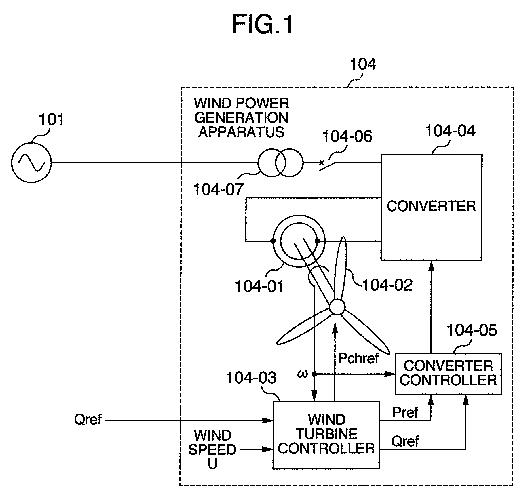
[0073]FIG. 1 is a single line diagram showing a system configuration according to an embodiment of the present invention. The configuration of a power system for electric power transmission will be explained below. Power generation equipment 101 of the power system can be simply considered as a power supply if it has a large capacity. The power from the power generation equipment 101 of the power system is transmitted to homes, buildings, factories, etc. via power lines.
[0074]A wind power generation apparatus 104 is connected to the power lines through a transformer 104-07 for coupling with the power system.
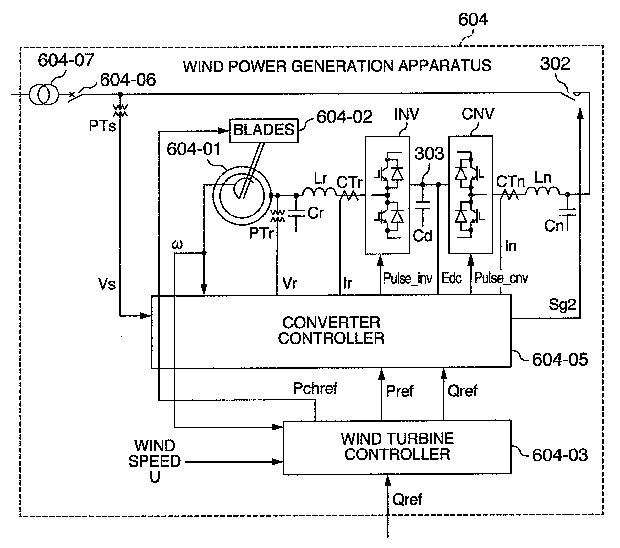
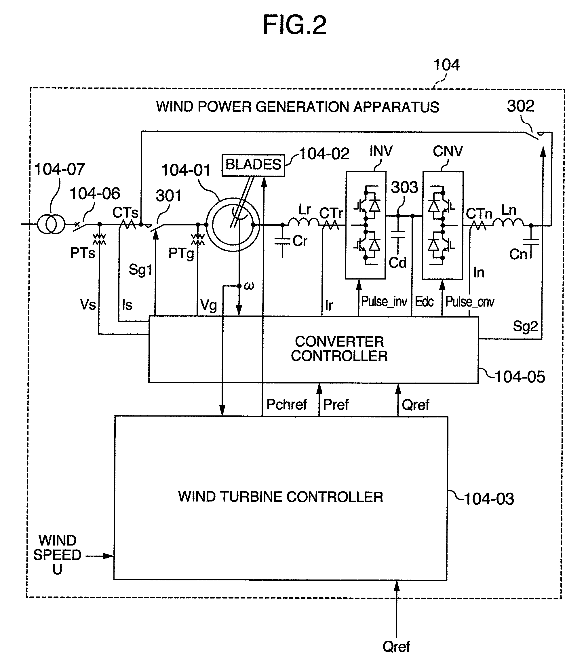
[0075]The wind power generation apparatus 104 includes mainly a wound-rotor induction generator 104-01, blades 104-02, a wind turbine controller 104-03, a converter (excitation apparatus) 104-04, and a converter controller 104-05.
[0076]The blades 104-02 are mechanically connected to the rotor of the generator 104-01 (through gears or the like). The rotor winding of the generator ...
embodiment 2
[0144]Another embodiment will be explained below with reference to FIGS. 6-8. The same symbols are assigned to elements having the same function as those in Embodiment 1, and duplicated explanations are omitted. Embodiment 2 uses a different method for creating an active power command Pref from that in Embodiment 1.
[0145]FIG. 6 shows the efficiency with which the wind turbine produces energy from wind. The horizontal axis indicates the ratio of the circumferential speed Vp1 [m / s] of a blade (end) relative to the wind speed U [m / s] (circumferential speed ratio X=Vp1 / U), and the vertical axis indicates the efficiency. As clearly shown in the FIG. 6, the efficiency is maximized at a certain circumferential speed ratio λ. The above-mentioned pitch angle table can be realized, for example, by obtaining in advance a pitch angle (at which rotating speed for a circumferential speed ratio with high efficiency can be obtained) from each wind speed value based on the characteristics in FIG. 7 ...
embodiment 3
[0153]Still another embodiment will be explained below with reference to FIGS. 9 and 10. FIG. 9 shows another embodiment of the wind turbine controller shown in FIG. 7. The same symbols are assigned to elements having the same function as those in Embodiment 1, and duplicated explanations are omitted.
[0154]The wind turbine controller 104-03 will be explained below with reference to FIG. 9. The wind turbine controller 104-03 inputs the wind speed U and detects an average wind speed Uav using a first order lag filter LPF or the like. The detected average wind speed Uav is input to the speed command calculating unit SCAL and power command calculating unit PREFCAL.
[0155]The power command calculating unit PREFCAL calculates an active power command value Pref using, for example, a table of average wind speed Uav relative to output power. As shown in the above-mentioned embodiment in FIG. 5, the power command calculating unit PREFCAL can be realized by obtaining in advance a table of power...
PUM
 Abstract
Description
Claims
Application Information
 - R&D
- Intellectual Property
- Life Sciences
- Materials
- Tech Scout
- Unparalleled Data Quality
- Higher Quality Content
- 60% Fewer Hallucinations
Browse by: Latest US Patents, China's latest patents, Technical Efficacy Thesaurus, Application Domain, Technology Topic, Popular Technical Reports.
© 2025 PatSnap. All rights reserved.Legal|Privacy policy|Modern Slavery Act Transparency Statement|Sitemap|About US| Contact US: help@patsnap.com


