Method for producing a cup-shaped object

a production method and cup-shaped technology, applied in the direction of closures, packaging, closure caps, etc., can solve the problem of enamel layer drawing filaments, and achieve the effect of greatly reducing or even completely eliminating filament or tail formation

Active Publication Date: 2010-02-16
MAIKO ENG
View PDF16 Cites 10 Cited by
  • Summary
  • Abstract
  • Description
  • Claims
  • Application Information

AI Technical Summary

Benefits of technology

[0008]Proceeding from this problem, the object is to improve the method explained at the outset in such a way that, in particular for high cycling times, filament or tail formation is greatly reduced or even completely eliminated.
[0013]The flange then has a maximum width of, e.g., 3 mm, which is very small compared to the height of the cup. The flange is deformed or deflected in a second step in a second tool, without impingement of force on a blank holder, so that no surface pressure acts on the flange during deflection. The necessary shaping force may be kept very low due to the only slight degree of shaping required, thus preventing cracking of the enamel layer and formation of filaments. Introduction of a profiling in the wall of the blank provided in the second step prepares the blank for further processing, such as curling the wall inward.
[0014]This method eliminates the shutdown time heretofore necessary for cleaning, and the associated costs, which significantly reduces the manufacturing costs. Since there are no filaments on the blank either, the additional work step and corresponding control steps previously required for removing the filaments are also omitted, which further lowers the manufacturing costs. In addition, tail formation is reduced. Besides the reduction in manufacturing costs, the quality of the product is increased.
[0016]An alternative embodiment of the method according to the invention provides that the deformation is performed by a guide which cooperates with the second tool. Lastly, a further alternative embodiment of the method according to the invention provides that the deformation is carried out by rolling in a second tool. The rolling renders possible a simple and efficient shaping method in order to prepare the blank for further processing.
[0017]The wall preferably is drawn radially outward by the profiling. Alternatively, the profiling causes the wall to deform facing radially inward. These embodiments of the profiling prevent folds or buckles from forming in the wall during a subsequent curling of the wall, which increases the quality of the finished cap. In addition, there is no need to tilt or slide the cap forward later in order to curl the edge.

Problems solved by technology

The cracking of the enamel layer on account of the excessive surface pressure would cause the enamel layer to draw filaments.

Method used


Image

  • Method for producing a cup-shaped object
  • Method for producing a cup-shaped object
  • Method for producing a cup-shaped object

Examples


Embodiment Construction

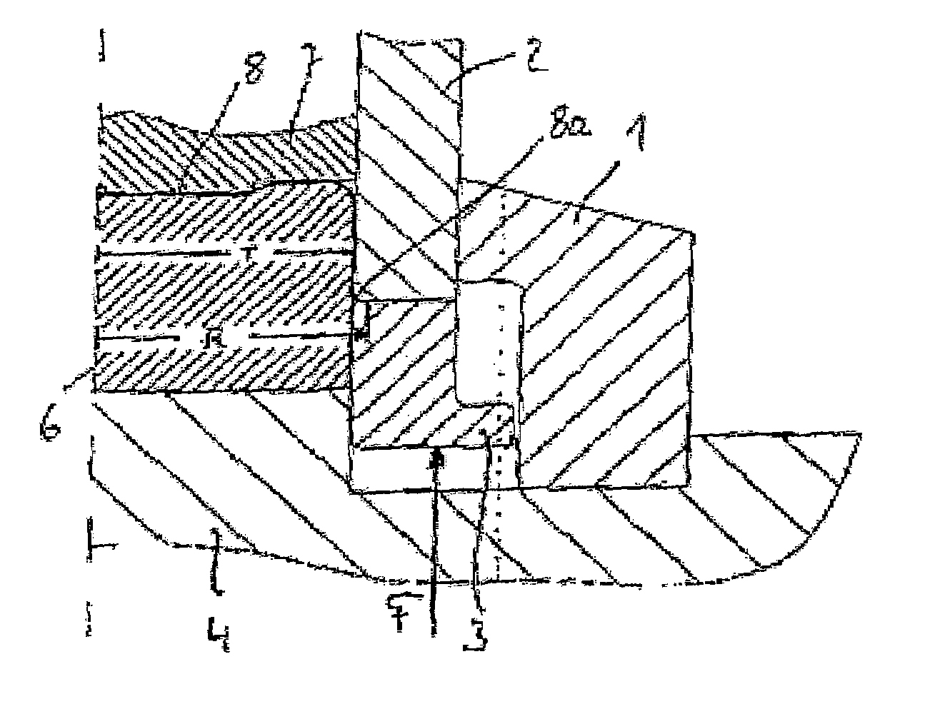
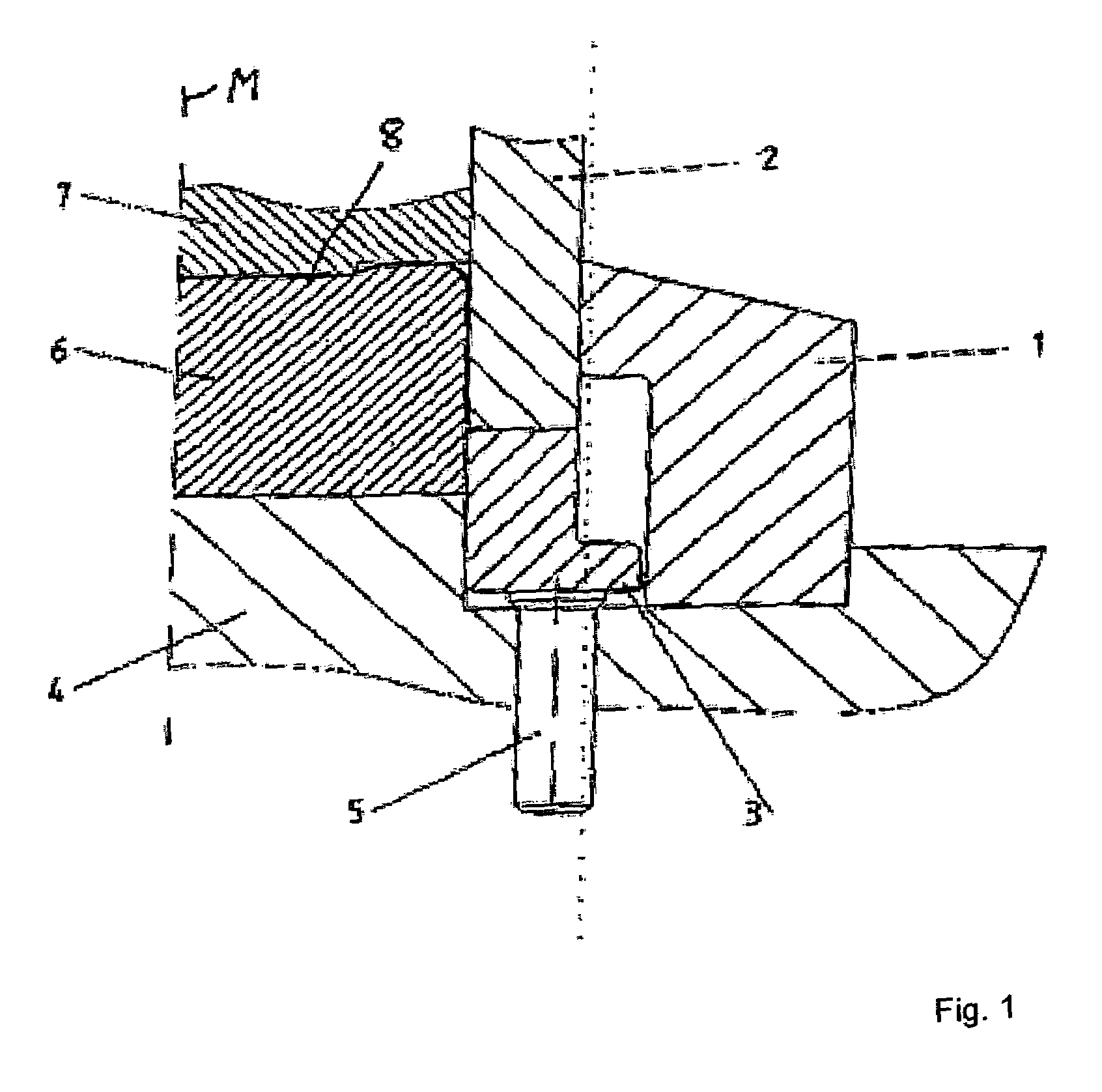
[0030]FIG. 1 shows a partial section of the first deep-drawing tool, symmetrically structured about the centerline M, comprising the cutting ring 1, the cutting bell 2, the blank holder 3 which cooperates with the cutting bell 2, the base 4 which supports the drawing block 6, and the stamping block 7. The stamping block 7 and the drawing block 6 together with the cutting bell 2 enclose the blank 8. The force from a spring assembly (not illustrated here in greater detail) is transmitted to the blank holder 3 via hold-down pins 5 arranged uniformly distributed on a peripheral circle.

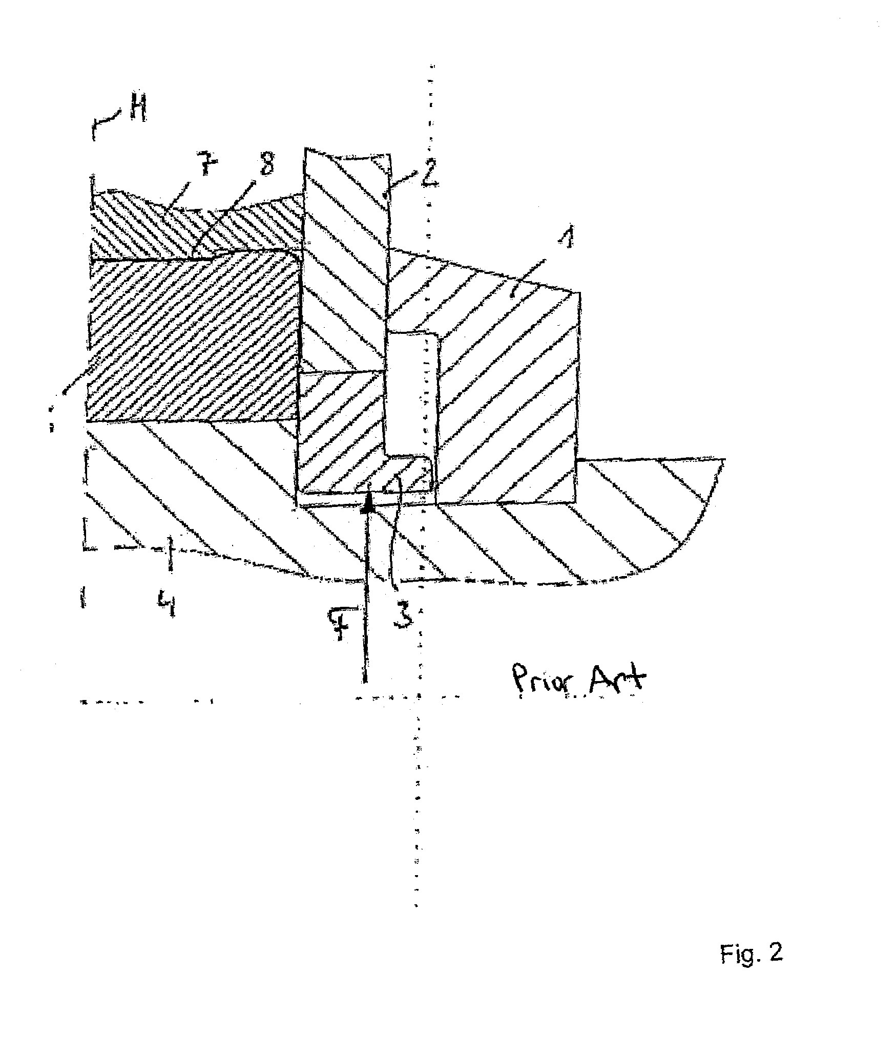
[0031]The blank 8 is produced according to the prior art using the tool according to FIG. 2, the enameled metal sheet or circular blank cut (stamped) therefrom by the cutting ring 1 being placed on the drawing block 6. The stamping block 7 and the cutting bell 2 are lowered onto the metal sheet, whereby the cutting bell 2 stamps a sheet metal plate from the circular blank. After the metal sheet is separate...


PUM

PropertyMeasurementUnit
radial width R-aaaaaaaaaa
widthaaaaaaaaaa
rotationaaaaaaaaaa

Abstract

A method for the production of a cup-shaped article, in particular a blank of a screw cap for glass bottles or the like, from an enameled metal sheet, using two tools in a stepwise manner: 1) the blank is stamped from the metal sheet in a first tool by the relative motion between a cutting bell cooperating with a blank holder and a drawing block, and the blank is drawn around the drawing block, the width of a flange forming between the cutting bell and the blank holder being continuously reduced with a progressive degree of deformation until the flange reaches a defined width (R-r), and 2) the blank is deformed in a second tool such that the radially outwardly directed flange is deflected toward a profiling introduced in a wall of the blank.

Description

FIELD OF INVENTION[0001]The invention relates to a method for the stepwise production of a cup-shaped article, in particular a blank of a screw cap for glass bottles or the like, from an enameled metal sheet, whereby in a first step the blank is stamped from the metal sheet by deep-drawing based on the relative motion between a cutting bell cooperating with a blank holder and a drawing block, and the blank is drawn around the drawing block, the width of a flange of the blank forming between the cutting bell and the blank holder being continuously reduced with a progressive degree of deformation.BACKGROUND DESCRIPTION[0002]Deep drawing is understood to mean the shaping of a sheet metal section (circular blank, plate blank) into a hollow body, or the shaping of a hollow body into a hollow body with a smaller circumference, with or without intentional modification of the sheet metal thickness. During shaping, segments of the blank must be folded up on the cylinder wall, with the parts ...

Claims


Application Information

Patent Timeline
Patent Type & Authority Patents(United States)
IPC IPC(8): B21D22/20B21D51/44B21D22/22B21D51/50
CPCB21D22/22B21D51/44B21D51/50
Inventor WARMBRUNN, KLAUS
Owner MAIKO ENG
Why Eureka
Try Eureka