[0009]Joints according to the present invention lend themselves to use in constructing these polyhedrons with alternating open and closed facets. Thus, for example, in a truncated cuboctahedron with rectangular, hexagonal, and octagonal facets, the rectangular facets can have
solid structural panels congruent therewith (closed facets) while the octagonal and hexagonal facets are open. In, for example, a rhombicuboctahedron with triangular facets, rectangular facets, and square facets, the triangular and square facets can be open. The open facets enhance the appearance of the structure and provide multiple aesthetic and utilitarian options. The open facets are available for use as, for example, windows or
doors. Having open facet makes it easier to construct.
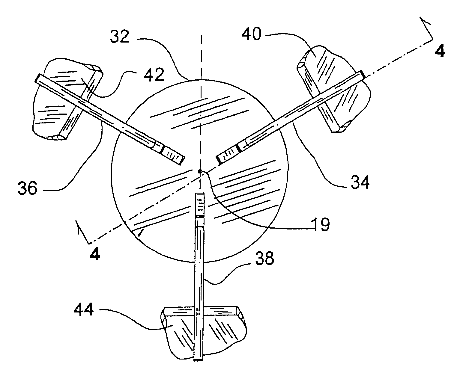
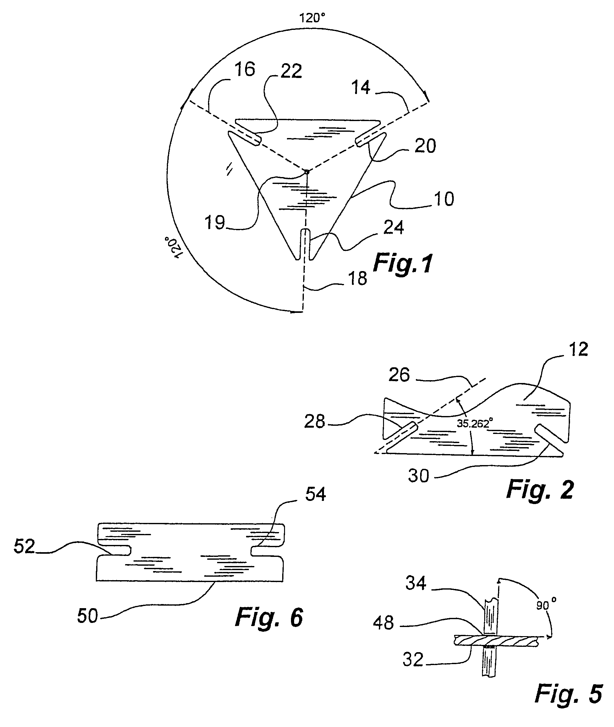
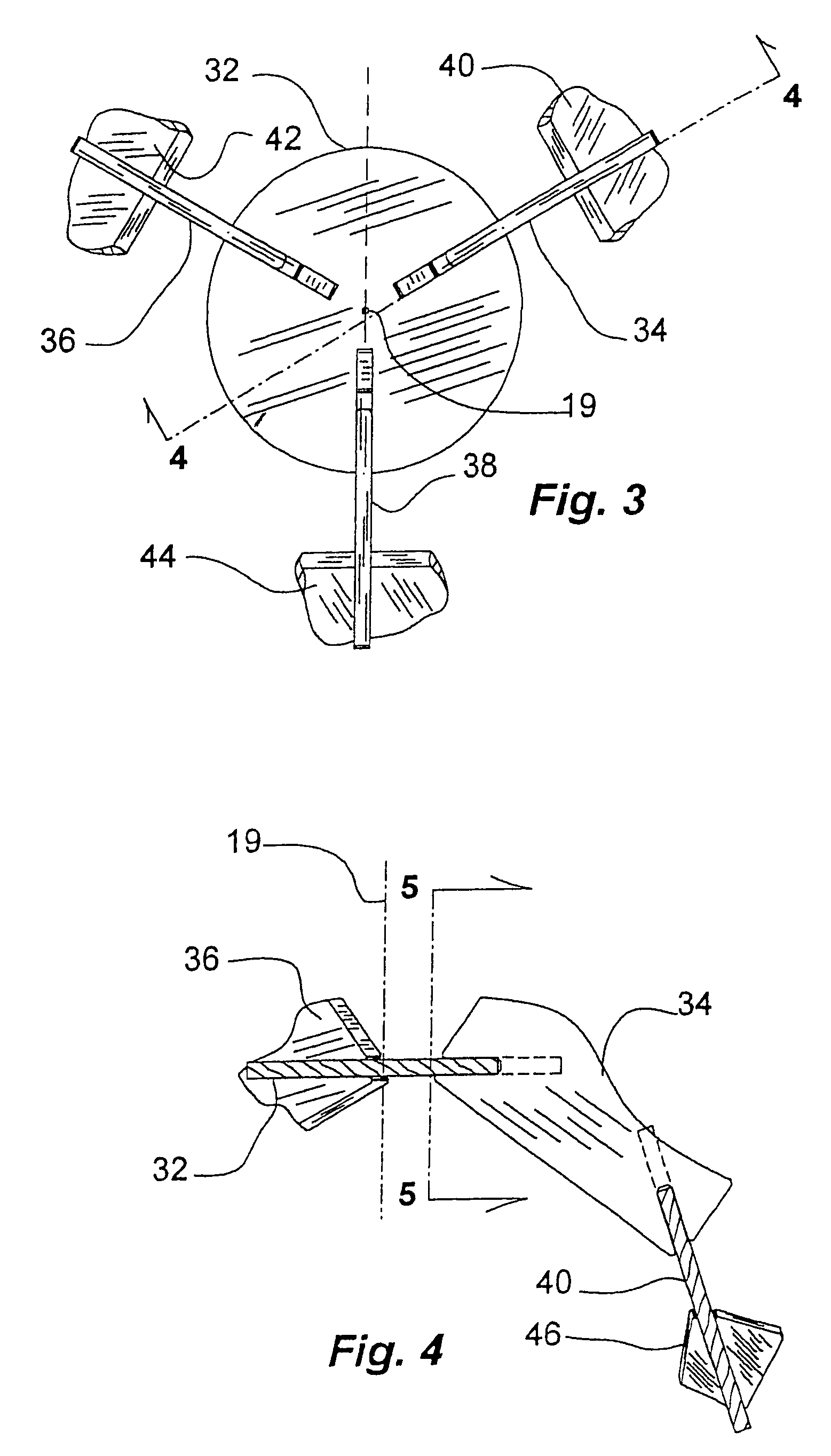
[0011]According to a further embodiment of the present invention, strong stable intra-polyhedron joints are easily and simply formed within a single convex polyhedron through the use of a key element perpendicularly engaged by and between two polyhedra elements. This joint structure requires only three engaged members for its construction. As with the embodiment of the joint system for joining two polyhedra together (inter-polyhedron joint), the intra-polyhedron joint is formed with the plane of the key element extending generally perpendicular to the respective planes of the two
mating polyhedra elements, and the planes of the polyhedra elements are generally congruent with the respective facets of the polyhedron. Each of the polyhedra elements in an intra-polyhedron joint typically joins two to four key elements. Each polyhedra element has a polyhedra element plane and at least one polyhedra element axis extending generally perpendicular to the polyhedra element plane. There is also a polyhedra joining axis associated with each joint that generally extends in the plane of the polyhedra element. When the joint is assembled, the polyhedra element joining axis is generally congruent with an associated key element joining axis. The key elements throughout the intra-polyhedron joint system are preferably identical except where the structure transitions to a different form such as, for example, a supporting base.
[0013]According to one embodiment, the joint system is assembled together by slidably interengaging straight slots in the polyhedra elements with
mating straight slots in the key element. In one simple embodiment, each of three uniformly radially arrayed straight slots in the inter-polyhedron key member is adapted to slidably interengage with a
mating slot in one of the other three elements to form a rigid connection. The engagement between the three elements in the intra-polyhedron embodiment is likewise by way of sliding
mutual engagement between straight mating slots formed perpendicular to the planes of the elements they are formed in. Because the elements of the joint structure in both the inter- and intra-polyhedron embodiments engage one another at right angles, the slots are easily formed by straight perpendicular cuts without the need for complicated tooling or difficult set ups. The simple inter- and intra-polyhedron embodiments of the joint structures, according to the present invention, are strong and stable without the need for further reinforcing expedients. Alternatively, other joining methods can be used as may be appropriate to the materials of construction. For example,
metal panels can be bolted or welded together without interpenetrating one another provided the required perpendicularity is provided. Structural adhesives, and the like, can be employed, if desired. Separate fastening elements such as, for example, bracket members, rivets, screws, bolts, and the like, can be employed to secure the polyhedra elements to the key members, as may be appropriate to the materials of construction. The joint elements can be composed of various construction materials including, for example, wood, concrete, lightweight concrete, plastics, plastic composites, aluminum, steel, other metals, and the like. The joint elements can be formed utilizing conventional forming procedures including, for example, molding,
casting, sawing, and the like. The perpendicular nature of the key elements permits the construction of very efficient strength to weight designs. Structural materials are very efficiently used. This permits close control and optimization of the structural design. Variations in the size of the polyhedra elements congruent with the facets of a polyhedron can be achieved, for example, by the use of splice elements.
[0014]The present joint system does not require the maintenance of unrealistically close tolerances in its construction. Conventional construction equipment in the hands of competent craftsmen is all that is necessary to produce a
solid, safe structure. The key elements for the inter-polyhedron embodiments are preferably all identical except in transition areas. This permits them to be made at a factory location under good
quality control and shipped in bulk to a construction site for
assembly. Tolerances of one to two tenths of a degree and five to twenty thousandths of an inch can be maintained under factory production conditions.
Assembly does not require keeping track of tailored pieces for numerous unique joints. Since they are all the same, within the permitted tolerances, a workman need only take the next available key or polyhedra element and put it into the structure at the location of the next joint. Likewise, most of the polyhedra elements are preferably identical. Some of the polyhedra elements are necessarily modified, for example, to form openings or foundation engaging structure, but the angular relationships remain the same. The key elements can also be modified, where necessary or desirable, to accommodate openings or transitions in the form of the structure. Again, however, the angular relationships remain the same. Preferably, such special cases are few in number so they can be dealt with efficiently. The joint systems of the present invention are tolerant of the misalignments that inevitably occur in on-site construction projects. Also, the joints retain their strength and safety when the structures settle or foundations shift slightly as is normal with new construction.


