
Phase matching of high order harmonic generation using dynamic phase modulation caused by a non-collinear modulation pulse

a dynamic phase modulation and high harmonic technology, applied in the direction of instruments, basic electric elements, laser details, etc., can solve the problems of significant modulation in both amplitude and phase of harmonics, the inability to use hhg, and the difficulty in optimizing the modulation period

Active Publication Date: 2010-02-16
UNIV OF COLORADO THE REGENTS OF
View PDF2 Cites 7 Cited by
  • Summary
  • Abstract
  • Description
  • Claims
  • Application Information

AI Technical Summary

Benefits of technology

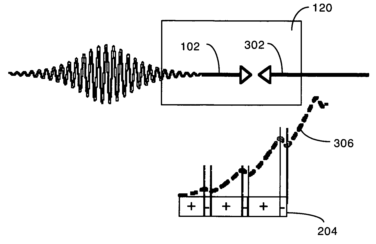
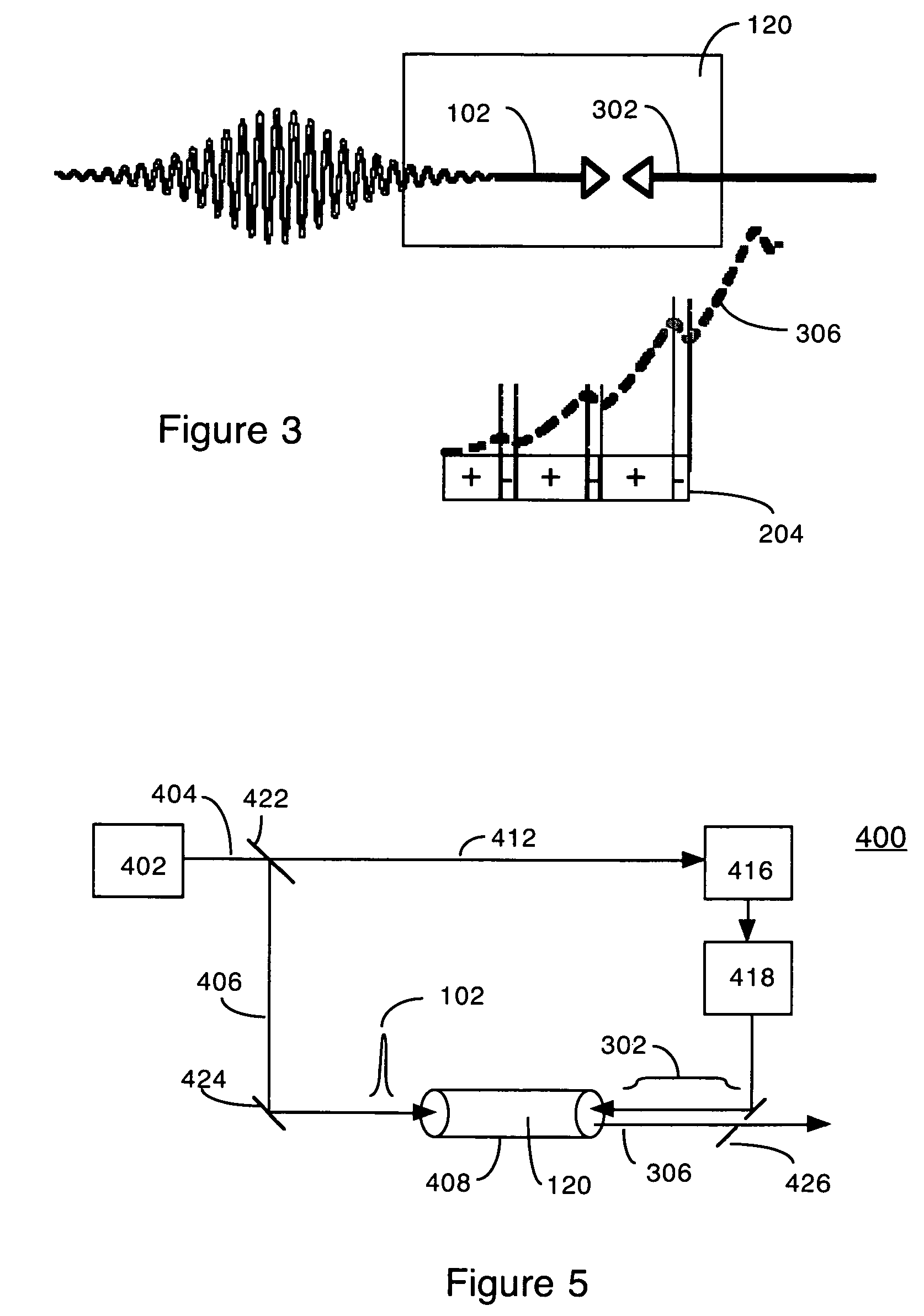
[0015]The HHG phase matching method of comprises the steps of: providing a volume filled with a gas, for example a noble gas such as argon, focusing a femtosecond (note that “femtosecond pulse” is defined herein to include pulses from a fraction of a femtosecond to a plurality of femtoseconds, i.e. what is termed in the field an “ultrashort light pulse”) driving pulse into the gas to cause high-harmonic generation (HHG), for example in the X-ray region of the spectrum, via electrons separating from and recombining with gas atoms, and providing a long duration non-collinear pulse to intersect the driving pulse and modulate the field seen by the electrons while separated from their atoms. The modulating pulse is low power and long duration (many times longer than the coherence length of the conversion process absent the modulating pulse), and its frequency and amplitude is chosen to improve HHG phase matching by increasing the areas of constructive interference between the driving pulse and the HHG, relative to the areas of destructive interference.
[0017]While the counterpropagating pulse is a long duration pulse (for example extending the length of the waveguide), it is advantageous to modulate the amplitude and wavelength of the pulse as it progresses (for example via pulse shaping). The intensity of the modulating pulse can be quite small—for example less than 1010 W / cm2, or 10−6 of the intensity of the driving pulse. Even though the modulating pulse is very long, its energy is still as little as 1 / 10 of that of the driving pulse, while resulting in many orders of magnitude increase in the x-ray yield. More than one modulating pulse may be used to fine-tune the response, but a single pulse of sufficient duration produces dramatic improvements.

Problems solved by technology

The major challenge is that, unlike low-order nonlinear processes such as second-harmonic generation, HHG is inherently associated with ionization of the nonlinear medium.
Thus, new methods that can correct for this phase mismatch in ionized media (plasmas) are a ‘grand challenge’ in this area of laser science.
However, this implementation cannot be used for HHG, because HHG uses a low-pressure gas as the nonlinear medium.
Even a small modulation (around 1%) of the driving laser results in significant modulation in both the amplitude and phase of the harmonics.
This is because optical loss of the driving laser, refraction, mode beating and group-velocity dispersion all result in a continuous variation of the coherence length along the direction of propagation, making it difficult to optimize the modulation period.
Finally, modulation periods shorter than the waveguide diameter will not significantly influence the laser field, making it challenging to compensate for very short coherence lengths.
However, this work only investigated harmonic emission in regimes where conventional phase-matching was already possible in the medium.
Attempts to obtain enhancements significantly greater than what could otherwise be obtained were not successful.
In addition, the counterpropagating pulses QPM technique is limited to the case where the coherence length is larger than ˜10-100 microns.

Method used


Image

  • Phase matching of high order harmonic generation using dynamic phase modulation caused by a non-collinear modulation pulse
  • Phase matching of high order harmonic generation using dynamic phase modulation caused by a non-collinear modulation pulse
  • Phase matching of high order harmonic generation using dynamic phase modulation caused by a non-collinear modulation pulse

Examples


Embodiment Construction

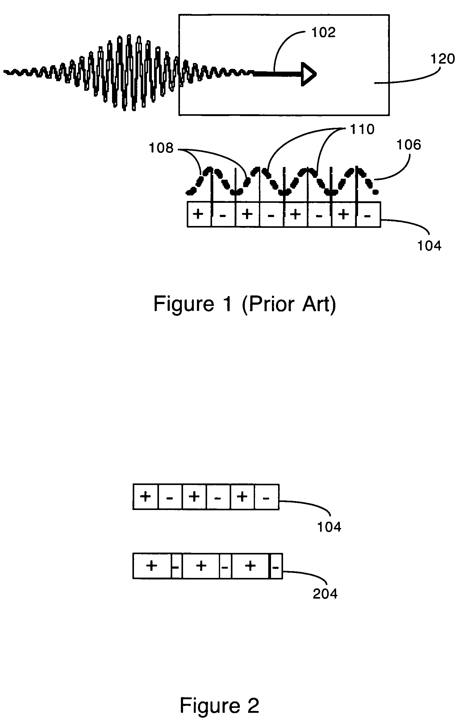
[0024]FIG. 1 (Prior Art) is a schematic diagram illustrating high-harmonic emission generation (HHG) without phase matching. Driving pulse 102 comprises a femtosecond laser pulse, which enters the HHG medium 120. Diagram 104 indicates the regions within the HHG medium in which constructive and destructive interference of HHG emissions will occur, due to the short coherence length of the HHG beam. The areas indicated by a plus (+) are areas of constructive interference, while the areas indicated by a minus (−) are areas of destructive interference. The length of one positively interfering area (+) in the absence of a modulating pulse is one coherence length.

[0025]Briefly, an ultrashort light pulse 102 is focused into a medium 120 (for example a noble gas) to generate high-order harmonics 106 in the vacuum-ultraviolet to x-ray regions of the spectrum (generally termed “x-ray HHG” herein). However, particularly for conversion to very short wavelengths, the high-harmonic process is not ...


PUM


Abstract

Phase matching high harmonic generation (HHG) uses a single, long duration non-collinear modulating pulse intersecting the driving pulse. A femtosecond driving pulse is focused into an HHG medium (such as a noble gas) to cause high-harmonic generation (HHG), for example in the X-ray region of the spectrum, via electrons separating from and recombining with gas atoms. A non-collinear pulse intersects the driving pulse within the gas, and modulates the field seen by the electrons while separated from their atoms. The modulating pulse is low power and long duration, and its frequency and amplitude is chosen to improve HHG phase matching by increasing the areas of constructive interference between the driving pulse and the HHG, relative to the areas of destructive interference.

Description

PRIORITY[0001]This application claims benefit of U.S. Provisional Patent Application No. 60 / 875,175, filed Dec. 15, 2006.[0002]U.S. patent application Ser. No. 11 / 888,916 is incorporated herein by reference.GOVERNMENT SUPPORT[0003]The present invention was made with the support of the U.S. government, which may have certain rights in this invention. Funding was provided by two sources: U.S. Department of Energy grant # DE-FG52-06NA26151, and The National Science Foundation grant # EEC0310717.BACKGROUND OF THE INVENTION[0004]1. Field of the Invention[0005]The present invention relates to phase matching in high harmonic generation (HHG) using a non-collinear pulse to modulate the field seen by the driving pulse. In particular, the present invention relates to such phase matching using a weak, long duration non-collinear modulation pulse intersecting the driving pulse.[0006]2. Description of the Prior Art[0007]High-order harmonic generation (HHG) driven by ultrashort laser pulses is a ...

Claims


Application Information

Patent Timeline
Patent Type & Authority Patents(United States)
IPC IPC(8): H01S3/30
CPCG02F1/353H05G2/001G02F1/3544G02F2001/354G02F1/354
Inventor COHEN, ORENKAPTEYN, HENRY C.MUMANE, MARGARET M.
Owner UNIV OF COLORADO THE REGENTS OF
Learn More