
System for construction of a compression structure with corner blocks, key blocks, and corner block supports

a compression structure and support technology, applied in the direction of parkings, foundation engineering, flooring, etc., can solve the problems of increasing construction site obstruction, inability to meet the requirements of construction, so as to save time and cost in the fabrication, simplify the design process, and reduce the effort and time required to design a structure for a given application.

Inactive Publication Date: 2010-02-23
POWELL DAVID W
View PDF32 Cites 20 Cited by
  • Summary
  • Abstract
  • Description
  • Claims
  • Application Information

AI Technical Summary

Benefits of technology

[0043]Because this system is intended to provide cost-effective, suspended structure, it can be built with a significant reduction in site grading and disruption as compared to conventional construction. Whether supported by drilled piers and pier caps, footing blocks, or another foundation system, variable-height footing blocks or base blocks can be “planted” on discrete foundations in a manner that can significantly reduce the excavation, cut and fill that is typical on most construction projects. By elevating the first level of floor structure above the ground, the cut and fill that is generally required for slab-on-grade construction can be largely eliminated, along with the runoff and erosion problems that often accompany extensive earthwork.
[0044]Block production is a highly efficient use of construction materials and manpower. Mold sets are built to be used repetitively; avoiding the waste of materials and manpower that often accompanies conventional concrete formwork, which is typically discarded after a very limited number of uses. The material that is normally wasted, and which presents a disposal problem, is minimized by reducing the number of times the concrete mixing and placing equipment must be cleaned, and by having very small blocks, such as cap blocks, that can be made of what might have otherwise been an overage of the castable material at the end of a production session. Combining a waste-conscious concrete pumping operation with an array of block sizes ensures that essentially 100 percent of the concrete that is produced will make its way into useful building product. This is in sharp contrast to the typical construction project that sends dumpsters full of waste to the landfill.
[0049]Because this building system is designed to offer a collection surface and structure for rainwater harvesting and storage, a building constructed of this system need not increase the effective impervious cover, and unnatural runoff, on a site. If this potential were combined with placing vehicle traffic and parking below or on the structure, the impervious cover of an entire project, and the eroding and polluting runoff that accompany it, can be reduced to become negligible. This may be combined with the potential, by building a collection terrace that is large enough, of harvesting and purifying enough rainwater to reduce or eliminate the occupant's need for a public water supply, and the infrastructure required to deliver it.
[0021]The building system is intended to introduce a unique line of large-scale building blocks to the construction industry, and to offer an expanding kit of parts from which quality structures may be quickly and economically built. It offers distinct advantages in the design, construction, and performance of the finished structure as compared with conventional construction utilizing structural steel, site-cast concrete, masonry, and wood-frame building systems. It also provides several environmental advantages to the growing numbers of people interested in “green” building, and has a wide variety of potential applications.
[0050]Many of the potential advantages of the building system and production methodologies described above have already been noted. It is expected that the list of advantages described herein will continue to grow as production methodologies and prototype structures are put into service and evolve.
[0051]The structure doesn't just give the impression of durability and stability; it can in fact be more durable and structurally sound than most conventional construction. The completed structural shell is more resistant to damage from structural overload, wind, fire, hail, flood, insects, and decay than are most standard construction types.
[0052]The creation of an access floor can allow extraordinary ease of MEP system integration and enormous flexibility in the subsequent reconfiguration of space. The provision of an access floor can position this system as a candidate for use in computer lab and cleanroom applications. The benefits of these features will continue to become more apparent amid the rapid evolution and continuous redefinition of information system technologies.
[0055]The long-term performance of this building system will provide direct and unique benefits to building owners and occupants. A structure built of these blocks is demountable; it can be easily modified, relocated, or traded in. The hardiness of the structure will qualify it for discounted insurance rates, and classification as a temporary structure may offer the owner some benefits relative to conventional construction in terms of reduced regulatory control and taxation of the construction. This system introduces building blocks as a commodity. As such, the purchase of a set of these building blocks represents a concrete investment option that also provides the owner with usable shelter or an income stream. These blocks cannot vanish overnight in the way many other investments can.

Problems solved by technology

The majority of structural design decisions that are made in conventional practice are driven by cost; there are enormous pressures on structural engineers of most building projects to minimize costs while upholding their first duty to ensure the safety of structures.
This tendency can be unfortunate when a structure is subjected to rare but extreme loads that cannot reasonably be incorporated into statistical load guidance provided by building codes.
Because much of conventional construction is inherently unstable until the construction of structural diaphragms and lateral systems are complete, structural failures during the relatively brief construction period are more common than in completed buildings that stand for years of service.
The lateral bracing and shoring that is typically required for conventional construction creates building site obstructions that contribute to many construction accidents.
Because conventional construction commonly involves the field assembly of parts that can be lifted and handled by one or two workers, the construction of exterior walls and roofs generally involves a significant amount of labor far above ground level; this creates the potential for falling hazards that generate the most lethal jobsite injuries.
Where conventional construction utilizes large parts, such as with tilt-wall construction, expensive crane time is typically consumed holding those parts in position while lateral shoring and bracing members and connections are installed; this is required to stabilize the part prior to releasing the hoisting lines.
The design of unique projects under ever-increasing time, budget, and liability pressures presents real challenges to design professionals; it also places an enormous burden on the builder that must interpret and build a unique and complex project from what will inevitably prove to be an imperfect set of drawings and specifications.
The use of on-site casting for concrete cast-in-place structures requires the expense and delay of field-fabricating the forms for pouring concrete.
Tilt wall construction provides some advantage in pre-casting wall elements, but has the disadvantage of requiring the advance construction of large areas of grade-supported slab to serve as a casting surface for the wall blocks.
Once conventional construction is complete, the modification or removal of a finished building generally involves destructive demolition.
This practice results in millions of tons of construction debris being hauled to landfills every year.

Method used


Image

  • System for construction of a compression structure with corner blocks, key blocks, and corner block supports
  • System for construction of a compression structure with corner blocks, key blocks, and corner block supports
  • System for construction of a compression structure with corner blocks, key blocks, and corner block supports

Examples


Embodiment Construction

General System Description

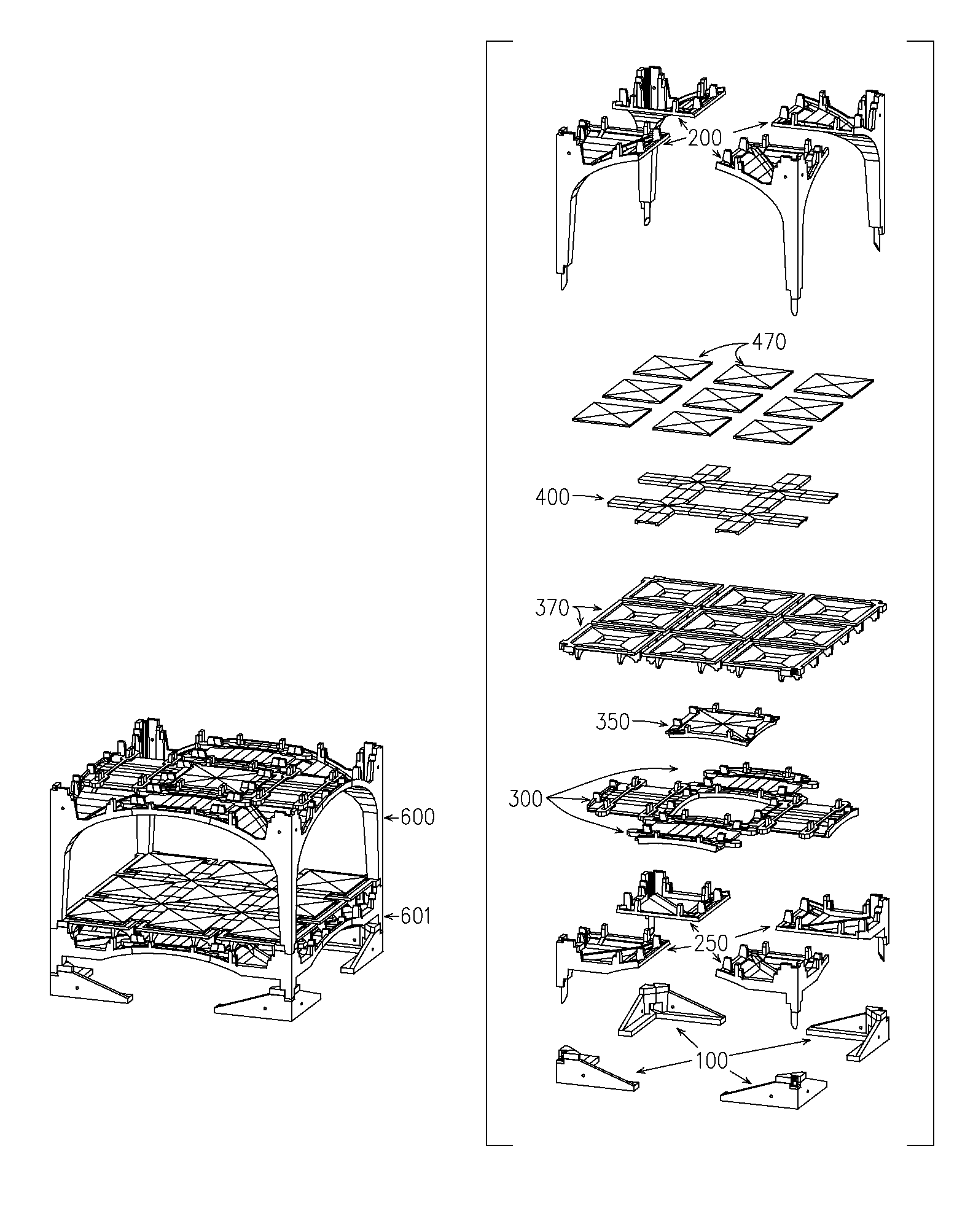
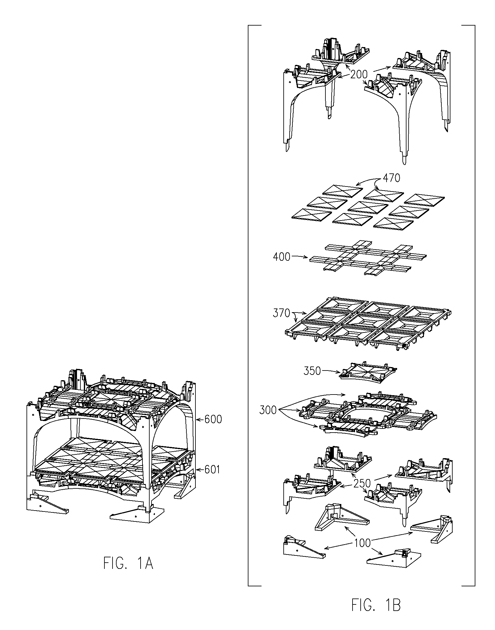
[0213]FIG. 1a shows an assembled structural module 600 that is composed of interlocking precast thin-shell blocks that are thickened and reinforced at selected locations in response to structural and detailing demands. FIG. 1B is an exploded view of the different elements which may include footing blocks 100, base blocks 250, corner blocks 200, key blocks 300, center blocks 350, pan blocks 370, cap blocks 400, and floor infill blocks 470. The assembled structural module 600 in FIG. 1A is shown supported on a base structural shell 601, in which corner blocks 200 are replaced by base blocks 250, which in turn are supported by footing blocks 100.

[0214]The building system and its variations are generally designed to carry forces in compression, where feasible to do so, because of the efficiency with which a compression structure utilizes building material.

[0215]Reinforced thin-shell concrete is typically used to make the blocks, however, the interlocking buildi...


PUM


Abstract

A structure assembled from a combination of stackable modules, each module assembled from multiple prefabricated, transportable blocks. The blocks are typically reinforced cast concrete formed in reusable molds. Module framing blocks may include arched corner blocks, key blocks that interlock with a pair of corner blocks, and optional center blocks. Other structural elements include roof, floor, and wall components that interlock with the framing modules. Modules may be stacked or nested to form structures including buildings, elevated roadways, and parking garages. Utilities may be provided through optional conduits formed in the corner elements. The framing supports raised floor modules for ease in mechanical system installation and modification. The roof elements support usable terraces and rainwater collection. The blocks are demountable and reusable. The modules are self-supporting during erection, and may be assembled without fasteners.

Description

RELATED APPLICATIONS[0001]This application is related to U.S. Provisional Patent Application No. 60 / 467,410 filed May 2, 2003, and claims the benefit of that filing date.BACKGROUND OF THE INVENTION[0002]1. Field of Invention[0003]This invention relates to a system of construction involving interlocking stackable precast blocks where a combination of interlocking and overlapping structural blocks are used to create individual structural frame modules; frame modules may then be nested and stacked with the necessary interlock to build larger structures.BACKGROUND[0004]Various uses of precast blocks are known in the prior art. In tilt wall construction, for example, precast wall panels are erected on a site to create a shell. Precast beams and planks are used in building construction and other civil engineering projects, such as bridges. Typically, this type of construction is used to build rectangular, box-like frame blocks which may require further support such as cross bracing.[0005]...

Claims


Application Information

Patent Timeline
Patent Type & Authority Patents(United States)
IPC IPC(8): E04B1/32E02D27/32E04H14/00E04B1/00E04B1/20E04B1/21E04B1/348E04B5/43E04B5/48E04C3/34E04F15/024
CPCE04B1/20E04B1/21E04B1/34823E04B5/43E04B5/48E04C3/34E04F15/02411E04B2001/0053
Inventor POWELL, DAVID W.
Owner POWELL DAVID W
Learn More