Wide-area fluorescence detection system for multi-photon microscopy

a fluorescence detection and multi-photon technology, applied in the field of microscopes and microscopy methods, can solve the problem of limited excitation to the focal plane, and achieve the effect of improving light collection

Active Publication Date: 2010-02-23
UNITED STATES OF AMERICA
View PDF10 Cites 2 Cited by
  • Summary
  • Abstract
  • Description
  • Claims
  • Application Information

AI Technical Summary

Benefits of technology

[0009]A multi-photon microscope according to an embodiment of the current invention has an illumination source, an objective lens unit arranged in an optical path of the illumination source, a first light collection system (usually associated with the microscope objective combined with a photo-multiplier tube, arranged to collect a first portion of light emitted from a sample when the sample is illuminated by light from the illumination source, and a second light collection system arranged to collect a second portion of light emitted from the sample, that is collecting light missed by the first light collection system, when the sample is illuminated by light from the illumination source. The first portion of light when collected by the first light collection system and the second portion of light when collected by the second light collection system, together provide enhanced light collection from the sample compared to light detected from the sample by only the first light collection system.

Problems solved by technology

In MPFM, the excitation is limited to the focal plane due to the level of spatial and temporal crowding of photons into diffraction limited spot.

Method used


Image

  • Wide-area fluorescence detection system for multi-photon microscopy
  • Wide-area fluorescence detection system for multi-photon microscopy
  • Wide-area fluorescence detection system for multi-photon microscopy

Examples


Embodiment Construction

[0015]In describing embodiments of the present invention illustrated in the drawings, specific terminology is employed for the sake of clarity. However, the invention is not intended to be limited to the specific terminology so selected. It is to be understood that each specific element includes all technical equivalents which operate in a similar manner to accomplish a similar purpose.

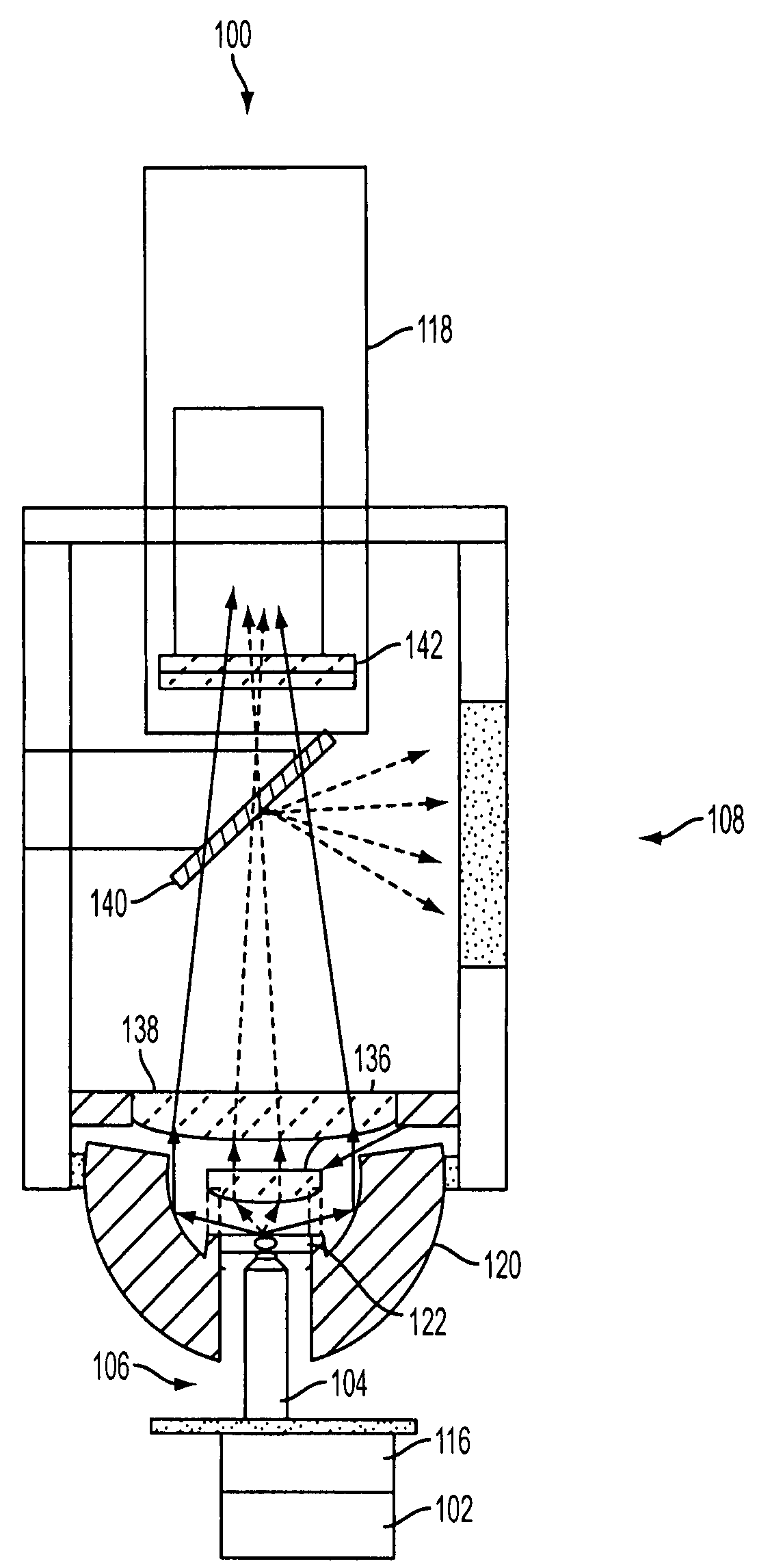
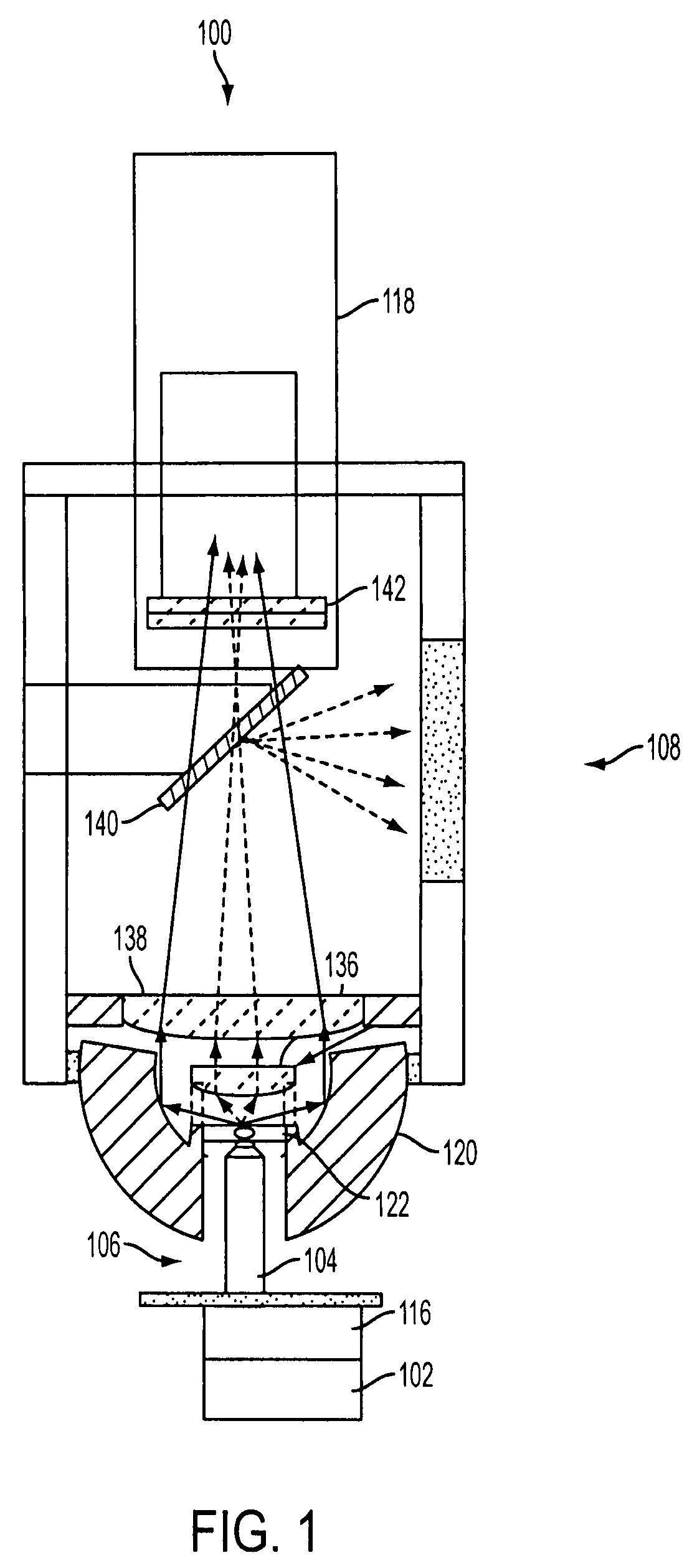
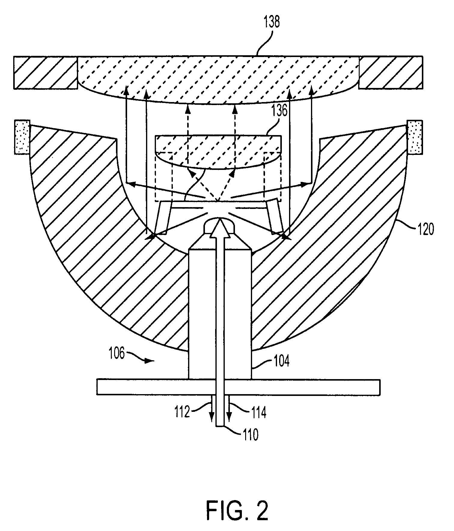
[0016]FIG. 1 is a schematic illustration of a multi-photon microscope 100 according to an embodiment of this invention. The multi-photon microscope 100 has an illumination source 102, an objective lens unit 104, a first light collection system 106 and a second light collection system 108. The objective lens unit 104 and first light collection system 106 are shown schematically in FIG. 2 on a larger scale. The objective lens 104 is arranged in an optical path of illumination light 110 from illumination source 102 (not shown in FIG. 2). Illumination light 110 from illumination source 102 is directed thr...


PUM


Abstract

A multi-photon microscope has an illumination source, an objective lens unit arranged in an optical path of the illumination source, a first light collection system arranged to collect a first portion of light emitted from a sample when the sample is illuminated by light from the illumination source, and a second light collection system arranged to collect a second portion of light emitted from the sample when the sample is illuminated by light from the illumination source. The first portion of light when collected by the first light collection system and the second portion of light when collected by the second light collection system, together provide a means of collecting as much light from as many angles as possible emanating from an emitting point source. This collection scheme has the potential to approach the total emission collection of light from an emitting point source depending on the optical properties of the sample being imaged.

Description

CROSS-REFERENCE TO RELATED APPLICATION[0001]This application claims priority to International Application No. PCT / US2007 / 017478, filed Aug. 6, 2007 and U.S. Provisional Application No. 60 / 835,462, filed Aug. 4, 2006, the entire contents of which are incorporated herein by reference.BACKGROUND[0002]1. Field of Invention[0003]This application relates to microscopes and methods of microscopy, and more particularly to multi-photon microscopes and multi-photon methods of microscopy.[0004]2. Discussion of Related Art[0005]The contents of all references, including articles, published patent applications and patents referred to anywhere in this specification are hereby incorporated by reference.[0006]Laser fluorescence confocal microscopy is an effective technique for producing three-dimensional images. Typically, the optical sectioning is achieved by placing a pinhole aperture in front of the emission detector. Alternatively, multi-photon fluorescence excitation microscopy (MPFM) technique...

Claims


Application Information

Patent Timeline
Patent Type & Authority Patents(United States)
IPC IPC(8): G01J1/58
CPCG02B21/06G02B2207/114
Inventor BALABAN, ROBERT S.COMBS, CHRISTIAN A.KNUTSON, JAY R.
Owner UNITED STATES OF AMERICA
Why Eureka
Try Eureka