Nuclear magnetic resonance module

a technology of nuclear magnetic resonance and modules, applied in the field of nuclear magnetic resonance tools, can solve the problems of unconsolidated sand formations, unfavorable mdt-type sampling tools, and low permeability of heavy oil reservoirs, and achieve low field and relatively low cost design, sufficient signal-to-noise ratio, and low cost

Active Publication Date: 2010-02-23
SCHLUMBERGER TECH CORP
View PDF21 Cites 13 Cited by
  • Summary
  • Abstract
  • Description
  • Claims
  • Application Information

AI Technical Summary

Benefits of technology

[0006]Aspects and embodiments of the invention are directed to a nuclear magnetic resonance (NMR) module that implements magnetic gradient fields to achieve a flexible, low-field and relatively low-cost design. The NMR apparatus may be used in connection with a variety of different tools or systems including, for example, a down-hole side-wall coring tool and various manufacturing process controllers. The magnet assembly may be constructed around a sample chamber such that a sample to be analyzed is contained within the NMR apparatus, allowing for the use of low strength magnetic fields while maintaining a sufficient signal-to-noise ratio for desired NMR measurements such as, for example, diffusion, relaxation time (e.g., longitudinal relaxation time T1 and / or transverse relaxation time T2), chemical shift, and other types of measurements known in the art. As discussed below, the magnet assembly may be constructed to provide a substantially uniform field in one or more directions and also a substantially non-uniform or gradient field in at least one direction. The magnetic field may be controlled through placement of the magnets around the sample chamber and thus, in at least one embodiment, field uniformity may be achieved without requiring specially designed, expensive, uniform magnets. This may allow for a robust and flexible design suitable for use in many different applications.
[0007]According to one embodiment, a nuclear magnetic resonance apparatus may comprise a sample chamber, a magnet assembly disposed about the sample chamber and constructed and arranged to provide a non-uniform magnetic field having a known magnetic field gradient inside the sample chamber, a radio frequency (RF) coil positioned so as to substantially surround the sample chamber, and a controller coupled to the RF coil and constructed and arranged to control the RF coil to produce an RF pulse sequence, and an RF power supply constructed and arranged to provide RF power to the RF coil to produce the RF pulse sequence. In one example, the magnet assembly may comprise a first permanent magnet disposed on a first side of the sample chamber, a second permanent magnet disposed on a second side of the sample chamber directly opposite the first permanent magnet, a first pole piece coupled to the first permanent magnet such that the first pole piece is positioned between the first permanent magnet and the sample chamber, and a second pole piece coupled to the second permanent magnet such that the second pole piece is positioned between the sample chamber and the second permanent magnet. In another example, the magnet assembly may further comprise a magnetic shield disposed so as to substantially surround the first and second permanent magnets, the first and second pole pieces and the sample chamber. In one example, the gradient and strength of the non-uniform magnetic field may be controlled by selecting a location and field producing capacity of the first and second permanent magnets. In another example, apparatus may further comprise a pulsed field gradient module. In another example, the apparatus may further comprise a pre-amplifier and a Q-switch, wherein the Q-switch is coupled between the pre-amplifier and the RF power supply and is constructed and arranged to reduce leakage from the RF power supply to the pre-amplifier during transmission of the RF pulse sequence.

Problems solved by technology

Mobility of heavy oil may be very low for reservoirs with low permeability or lower temperatures.
However, it is uncertain whether any of these strategies will reliably reproduce samples that are identical to the native formation fluids.
Furthermore, unconsolidated sand formations may present additional challenges for MDT-type sampling tools.

Method used


Image

  • Nuclear magnetic resonance module
  • Nuclear magnetic resonance module
  • Nuclear magnetic resonance module

Examples


Embodiment Construction

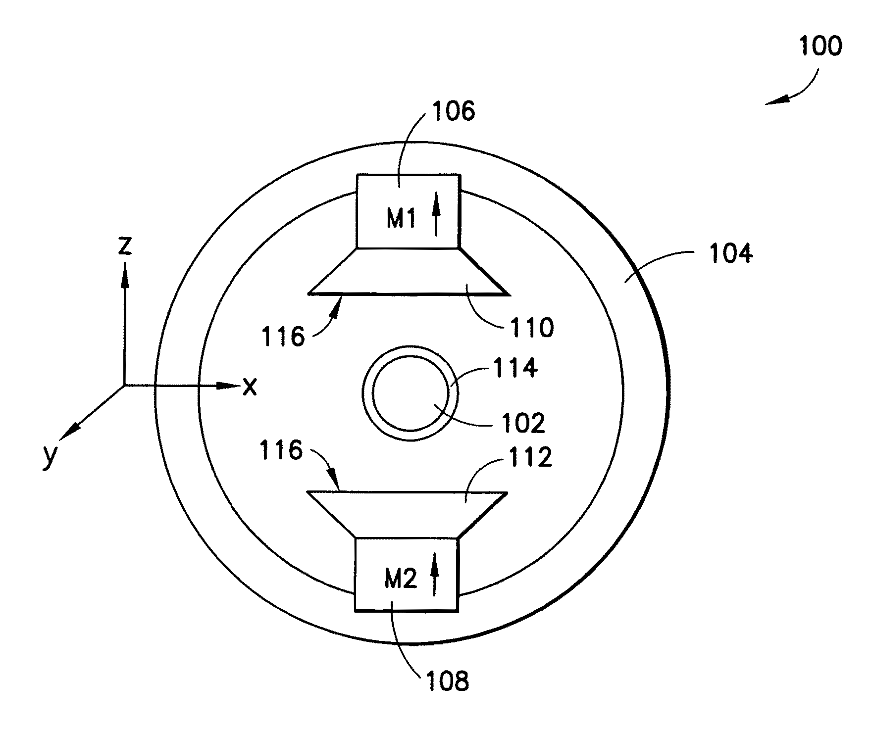
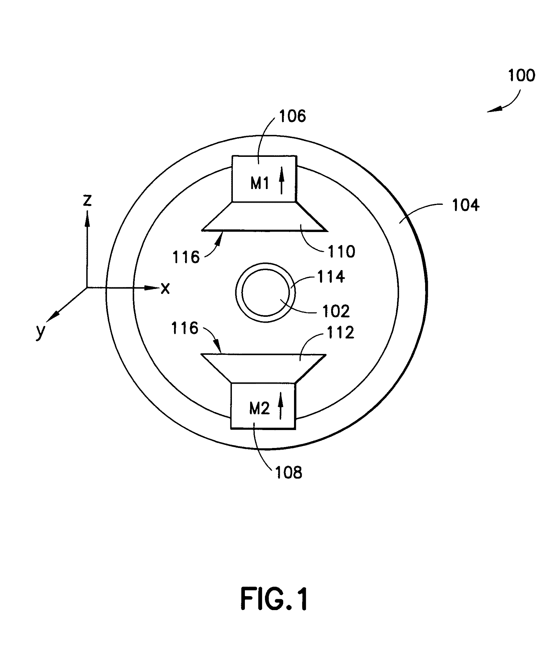
[0022]Embodiments of the invention are directed to a nuclear magnetic resonance apparatus that may be used in connection with a variety of different tools, including a down-hole side-wall coring tool as well as with manufacturing process controllers. Unlike many traditional NMR modules that may be designed around achieving as uniform a magnetic field as possible, embodiments of the NMR apparatus according to the invention may be designed to have an intentionally non-uniform magnetic field in at least one direction. Instead of being substantially uniform, the magnetic field may have a known, and in some embodiments constant, field gradient in one or more directions. The use of gradient fields may allow for a more flexible and inexpensive magnet assembly design, as discussed below.

[0023]It is to be appreciated that this invention is not limited in its application to the details of construction and the arrangement of components set forth in the following description or illustrated in t...


PUM


Abstract

A nuclear magnetic resonance apparatus that may be used in connection with a variety of different tools, including a down-hole side-wall coring tool as well as with manufacturing process controllers. In one embodiment, the nuclear magnetic resonance apparatus may include a magnet assembly constructed around a sample chamber. The magnet assembly is constructed and arranged to provide a non-uniform magnetic field having a known magnetic field gradient inside the sample chamber. The use of gradient fields may allow for a more flexible and robust magnet assembly design that may be suitable for a variety of different applications.

Description

BACKGROUND[0001]1. Field of Invention[0002]The present invention relates to nuclear magnetic resonance tools.[0003]2. Discussion of Related Art[0004]Nuclear magnetic resonance (NMR) has become a common wireline logging service and it has been used extensively to estimate properties of rocks (such as porosity, permeability, bound fluid, etc.) and fluids (for example, saturation, viscosity, oil and gas percentage, etc.). NMR measurements, in general, are accomplished by causing the magnetic moments of nuclei (“spins”) in a formation to precess about an axis. The axis about which the nuclei precess may be established by applying a strong, polarizing, static magnetic field (B0) to the sample to align the proton spins in a direction parallel to the applied field. Next, a series of radio frequency (RF) pulses are produced so that an oscillating magnetic field B1 is applied to the sample. The static B0 and oscillating B, fields should be substantially perpendicular to one another. The RF p...

Claims


Application Information

Patent Timeline
Patent Type & Authority Patents(United States)
IPC IPC(8): G01V3/00
CPCG01N24/081G01R33/3806G01R33/383G01R33/5617G01V3/32G01R33/421G01N24/08G01R33/30
Inventor SONG, YI-QIAOGAYLOR, RICHARD
Owner SCHLUMBERGER TECH CORP
Why Eureka
Try Eureka