
Quantum bit reading device and method

Active Publication Date: 2010-02-23
KK TOSHIBA
View PDF3 Cites 3 Cited by
  • Summary
  • Abstract
  • Description
  • Claims
  • Application Information

AI Technical Summary

Benefits of technology

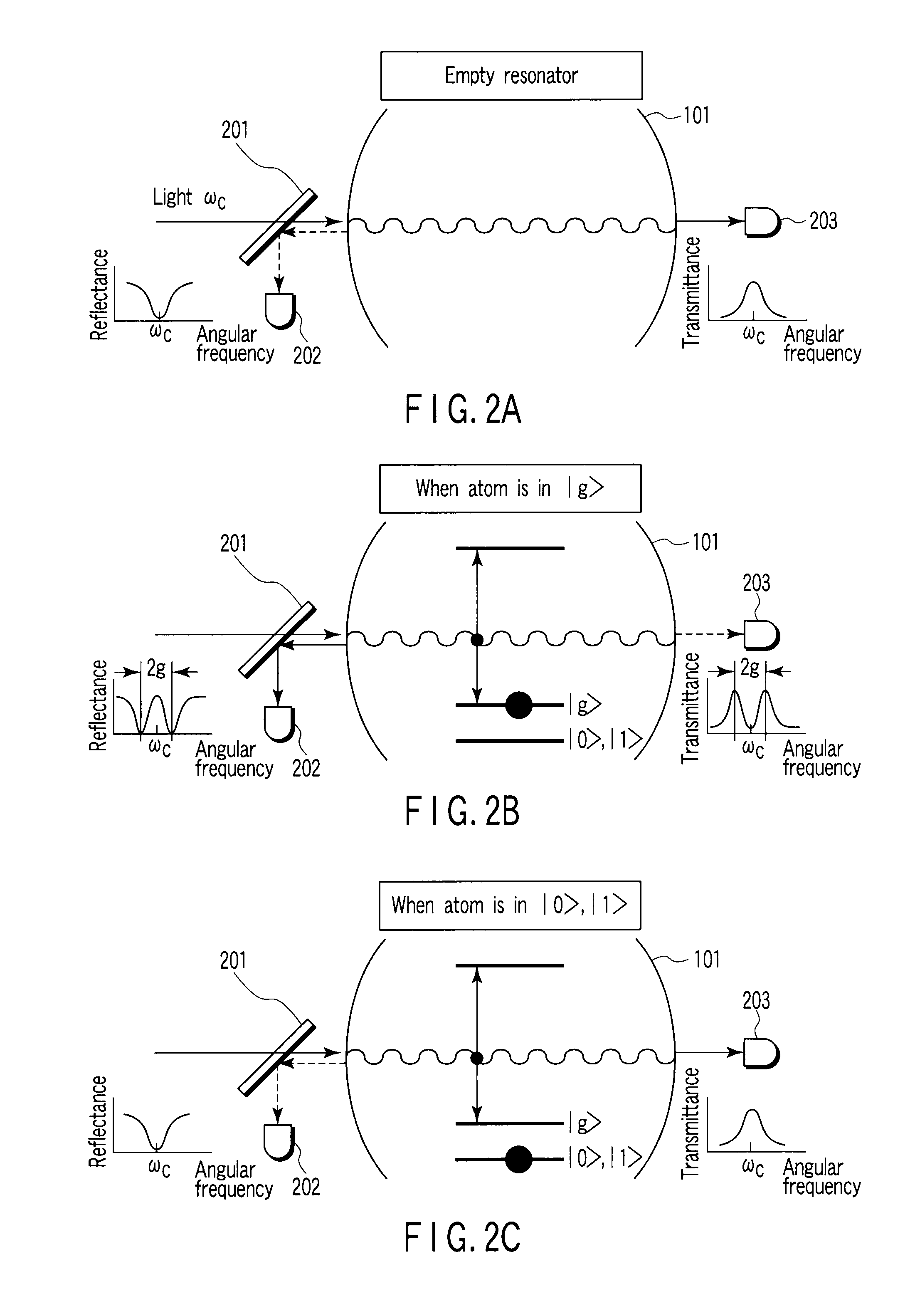
[0018]The quantum bit reading device and quantum bit reading methods of the embodiment and examples can read individual quantum bits that exist in a resonator and each comprise a single physical system (a single atom, ion, etc.), by detecting significant changes in the intensity of sufficiently intensified light.

Problems solved by technology

However, a specific method of using the response of the coupled system formed of the resonator mode and each physical system to read a plurality of quantum bits existing in a single resonator is not known so far.

Method used


Image

  • Quantum bit reading device and method
  • Quantum bit reading device and method
  • Quantum bit reading device and method

Examples


example 1

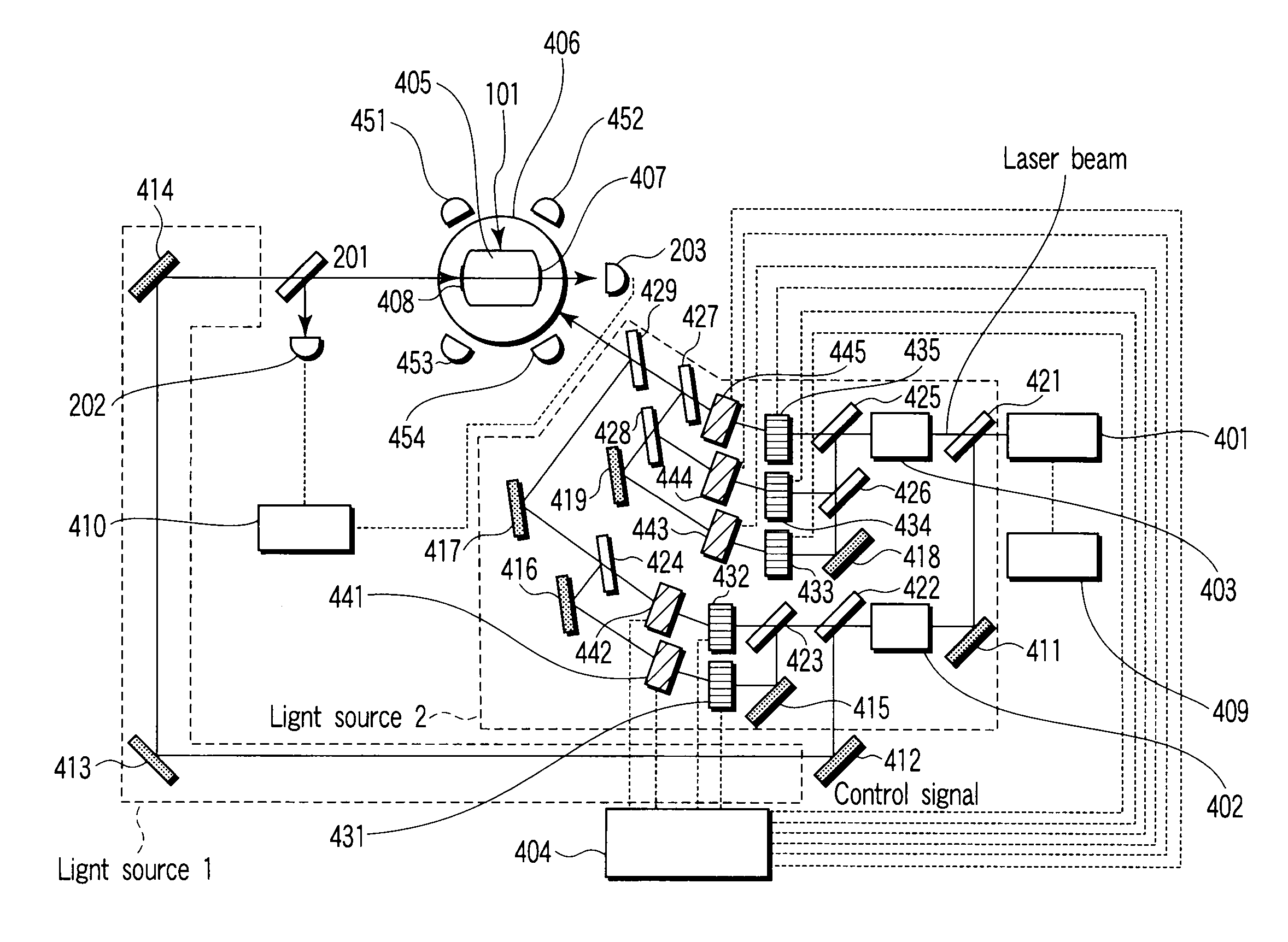
[0062]In the quantum bit reading apparatus and method employed in example 1, a Pr3+ ion contained in Pr3+:Y2SiO5 crystal, which is obtained by replacing 10−5% Y3+ ions in Y2SiO5 with Pr3+ ions, is used as a quantum bit. This crystal has a size of about 10 mm ×10 mm×10 mm, and is provided with a mirror of an ultra high reflectance on its surface. Thus, a resonator structure is provided. The resonator mode of the resonator is designed such that the resonator structure resonates with a transition (approx. 494.73×2πTHz) of a Pr3+ ion between 3H4 and 1D2. The mode west radius is approx. 1 μm. The crystal is installed in the cryostat and held at 1.5K.

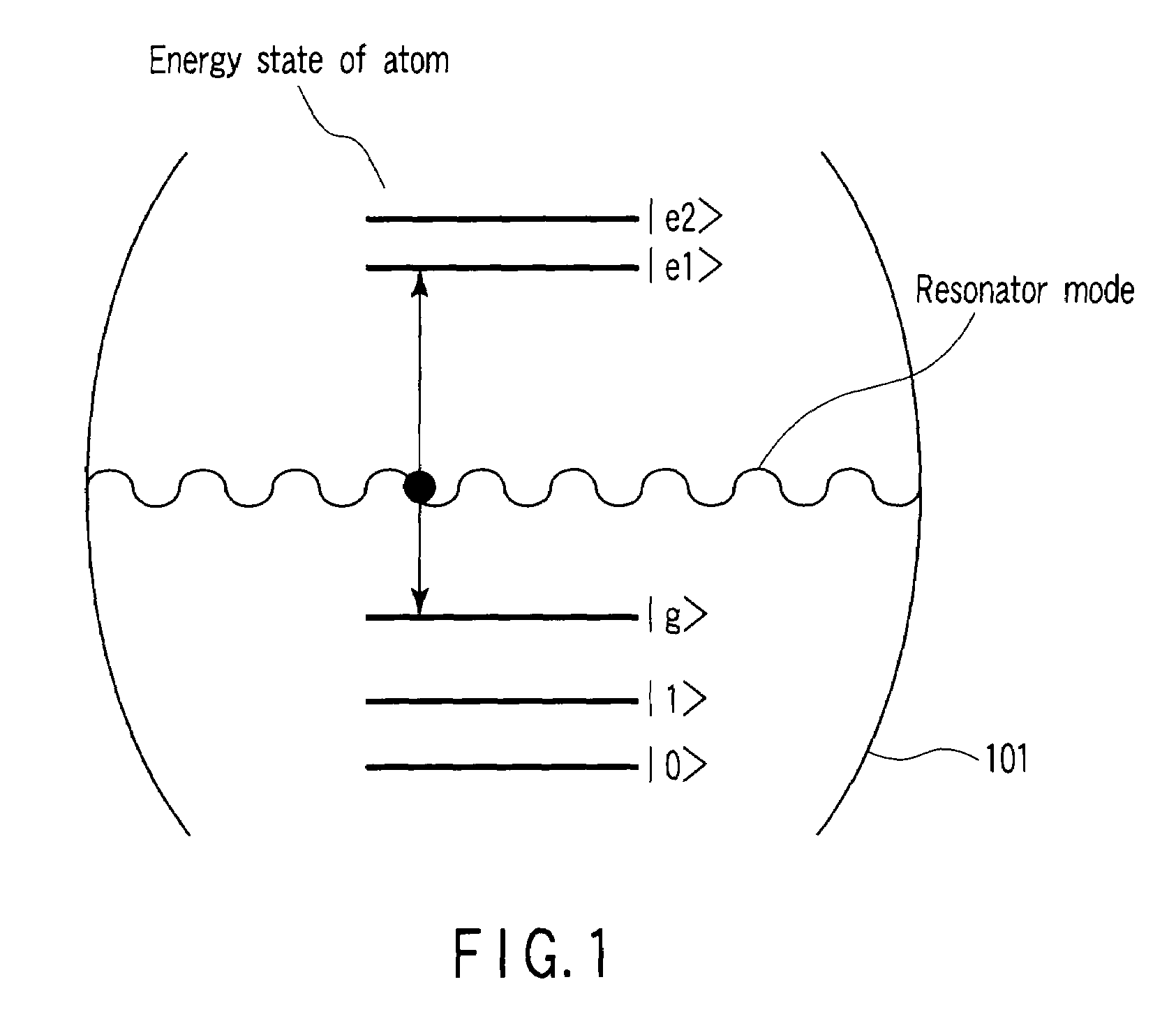
[0063]The Pr3+ ion contained in Pr3+:Y2SiO5 crystal can assume the energy states shown in FIG. 5. 3H4 has three energy states (|±5 / 2>, |±3 / 2> and |±1 / 2> in the increasing order), and 1D2 also has three energy states (|±1 / 2>, |±3 / 2> and |±5 / 2> in the increasing order). The three energy states of 3H4, i.e., |±5 / 2>, |±3 / 2> and |±1 / 2>, will herei...

example 2

[0086]In example 2, the same devices as the resonator-attached crystal 405 and its peripheral devices employed in example 1 are used. Example 2 differs from example 1 in method. Specifically, in example 2, light of angular frequency ωc is introduced to the resonator-attached crystal 405, and the intensities of the light reflected therefrom are measured to read quantum bit 1. After that, the state of quantum bit 1 is changed from |g> to another state. At this time, light ω1 (1) is sufficiently introduced from the light source 1 to the crystal to shift the state |g> to another state, utilizing excitation to |e2> and relaxation to |0> or |1>, instead of utilizing adiabatic passage based on two light beams of different wavelengths, as in example 1.

[0087]As described above, a plurality of quantum bits existing in a double-sided resonator and each formed of a single physical system can be individually read by detecting a significant change in the intensity of sufficiently intensified ligh...


PUM


Abstract

An apparatus includes a material in a resonator and containing systems, each of the systems having five energy states, a unit generating first and second pulse that resonate in a second transition and a third transition, respectively, a unit controlling the first and second pulse to make the first and second pulse temporally overlap each other to obtain third light, a unit emitting the third light to each system, a unit generating observation light to be coupled to the resonator mode, a unit introducing the observation light to the resonator from an outside thereof, a unit reading one of quantum bits by measuring an intensity of one of reflected light and transmitted light of the observation light, a unit controlling the first and second pulse to make the first and second pulse temporally overlap each other to obtain fourth light, and a unit emitting the fourth light to each system.

Description

CROSS-REFERENCE TO RELATED APPLICATIONS[0001]This application is based upon and claims the benefit of priority from prior Japanese Patent Application No. 2007-071087, filed Mar. 19, 2007, the entire contents of which are incorporated herein by reference.BACKGROUND OF THE INVENTION[0002]1. Field of the Invention[0003]The present invention relates to a quantum bit reading device and method, in which a plurality of quantum bits, each of which comprises a single physical system and exists in a double-sided resonator, are individually read by detecting a significant change in the intensity of sufficiently intensified light, utilizing the phenomenon that the intensities of light beams reflected from and transmitted through a coupled system formed of the resonator mode of the resonators and each physical system (single atom, ion, etc.) are significantly changed in accordance with the state of each physical system, regardless of whether the intensity of incident light is high or less.[0004]...

Claims


Application Information

Patent Timeline
Patent Type & Authority Patents(United States)
IPC IPC(8): G01B9/02
CPCB82Y10/00G06N99/002G06N10/00
Inventor ICHIMURA, KOUICHIGOTO, HAYATO
Owner KK TOSHIBA
Learn More