For example, the design of each tube carried by a jet airliner typically takes about 40 hours on average.
This means that the output of the design
system is not expected, or relied upon, to be correct to within a certain crude tolerance.
Therefore, small errors in the design can be affordably worked-out by the persons of skill installing the pipes, such as by
cutting and shaping them to the necessary dimensions in situ.
First, many design domains, especially aircraft, are
highly sensitive to weight and other performance measures.
For example, it would typically be unacceptable for a large tube on an airliner be one inch longer than necessary, subject to the design constraints.
Second, each tube in an
airplane is typically labored over by a human designer or team of designers for many hours.
Accordingly, a conventional
system suited to the design of pipes in a building is generally far too crude for designing tubes in such objects as an
airplane, a
jet engine, or a
rocket motor.
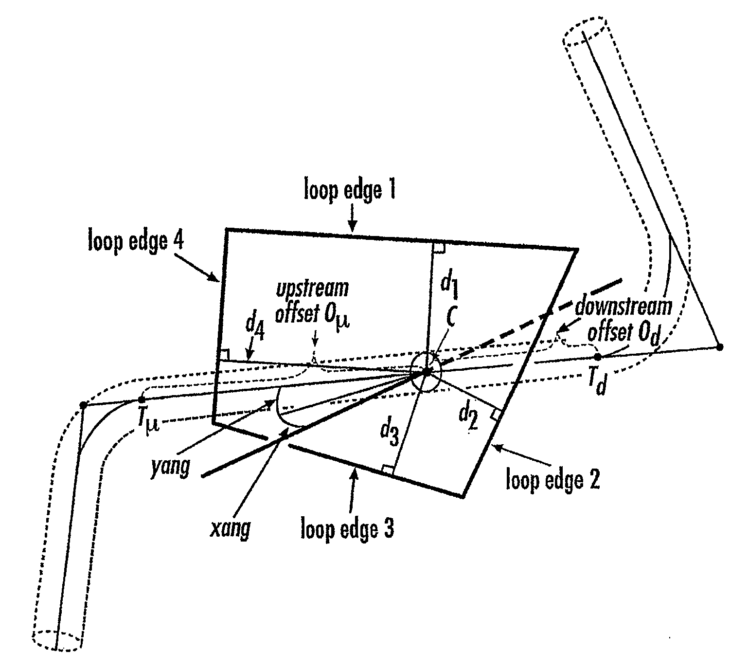
A tube is one type of transport element that poses a number of challenges in its design due to limitations upon the way in which the tube may be bent as described below.
As a result of constraints placed upon tube design by the manufacturing process, the straight sections and circular arcs each have a minimum length such that it is impossible to have an arbitrarily small bend, and one bend cannot begin an arbitrarily small distance from another bend.
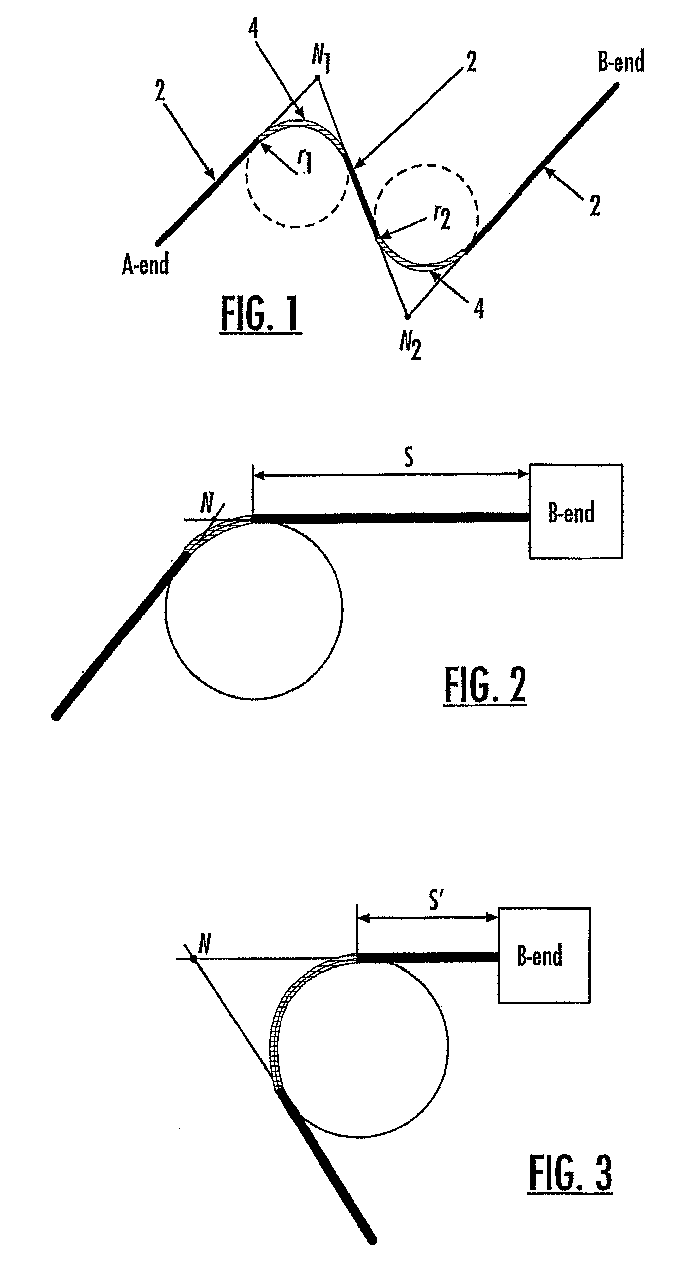
While nodes form a compact and intuitive representation of a tube, the use of nodes in the design of tubes may sometimes create problems.
However, if the segment of the tube upstream of node N is modified as shown in FIG. 3, the standoff S′ will shrink to an unacceptable level even though the node that defined the standoff was supposedly correct.
Nevertheless, even though the node does not define the standoff directly and may therefore be somewhat problematic during the
design process, nodes are frequently utilized in the design of tubes because of their simplicity and intuitive appeal.
Unfortunately, designers cannot generally select the specific route to be optimal for a transport element and currently have no automated techniques for doing so.
This manual drafting is typically a slow and difficult process.
The difficulty lies, however, in ensuring—in the face of the difficulties attached to node-based design just described—that the resulting route is manufacturable, satisfies
engineering constraints and is optimal.
These constraints typically arise from the nature of
tube bending machines.
Typically, it is expensive to change the circular die.
In addition, the
machine must be able to grip the stock during the formation of a bend such that the bending head has a certain amount of clearance, i.e., a new bend cannot be started arbitrarily close to the previous bend.
Nevertheless, the
compass, even with all the operations it provides, only supports what is still an essentially manual, sequential drafting process.
However, conventional CAD systems do not provide the designer with any alternative suggestions for a comparable tube segment that would comply with the rules and do not consider any redesign of the previously frozen portion of the tube design.
If the post hoc check determines that one or more of the segments does not comply with the rules, the route of the transport element must be redesigned, thereby consuming a significant amount of additional time and resources.
Transport element designs are not always final.
This is another area in which conventional tubing
design systems are lacking.
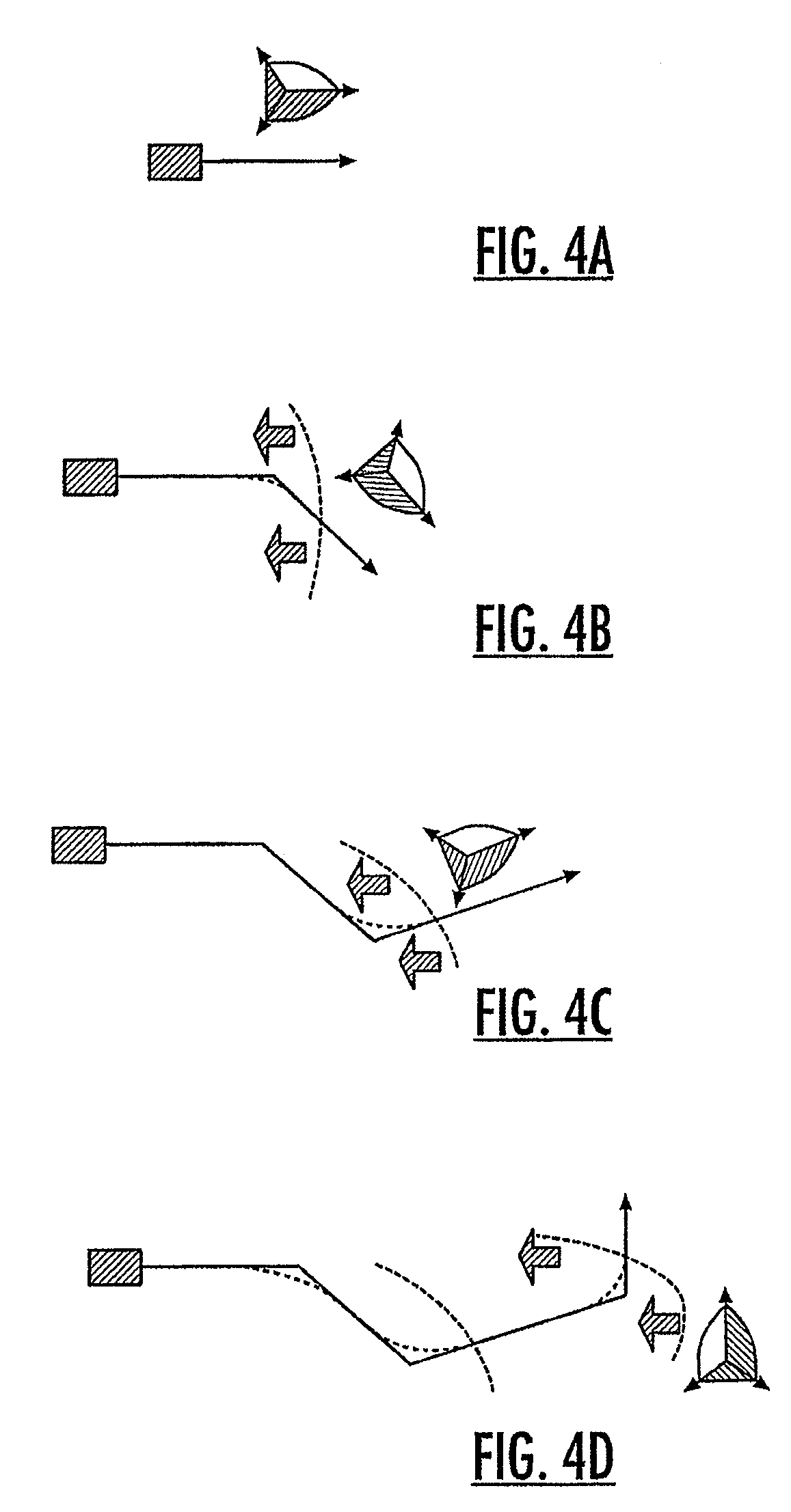
Thus, conventional CAD systems do not respond in a global way to local influences or changes—even if optimality would demand it.
The problem with this is that the optimal (e.g., shortest) redesign is very seldom obtainable by merely local adjustments.
Put in mathematical terms, conventional CAD systems do not permit one route to be continuously deformed into another unless they have the same node distribution.
The requirement that a human always design the node distribution for a route is a primary deficit of conventional tubing
design systems.
Conventional CAD systems do not effectively address the potential for designing the route of a transport element based at least in part upon one or more existing or contemporaneously designed transport elements.
Further, while pre-defined path constraints, such as parameterized stay-out zones such as boxes, cylinders, and spheres, may be used to represent spatial regions or objects which a transport element should circumvent, penetrate, or pass through for routing, pre-defined path constraints may not accurately represent an object and / or may be computationally intensive to implement when attempting to approximate fine details and complicated shapes, particularly if parameterized shapes would be used for regularly-sampled distance fields.

