Passive optical network (PON) system

a technology of optical network and optical fiber, applied in data switching networks, multiplex communication, star/tree networks, etc., can solve the problem that frames destined for another onu cannot be transferred, and achieve the effect of reducing the transfer frame length and effectively utilizing the bandwidth of the pon section in optical communication

Inactive Publication Date: 2010-03-09
HITACHI LTD
View PDF6 Cites 73 Cited by
  • Summary
  • Abstract
  • Description
  • Claims
  • Application Information

AI Technical Summary

Benefits of technology

[0021]In this case, the downstream frame processing unit of each ONU adds at least the destination MAC address, source MAC address, and protocol type of the L2 header in the content of the payload of a received frame from the passive optical network. If the header information other than the layer 2 header can be regenerated in the downstream frame processing unit of an ONU, it is possible to further reduce the length of a transmission frame in the PON section, by removing other header information as well as the layer 2 header information in the downstream frame processing unit of the OLT.
[0025]According to the present invention, by removing unnecessary information from a transferred frame in the PON section and thereby reducing the transferred frame length, it is possible to utilize the bandwidth of the PON section effectively in optical communications.

Problems solved by technology

However, in the PON system, part of the optical fiber section is shared by a plurality of ONUs, and consequently while a frame destined for a particular ONU (or user terminal) is transferred in the PON section, a frame destined for another ONU cannot be transferred.

Method used


Image

  • Passive optical network (PON) system
  • Passive optical network (PON) system
  • Passive optical network (PON) system

Examples


Embodiment Construction

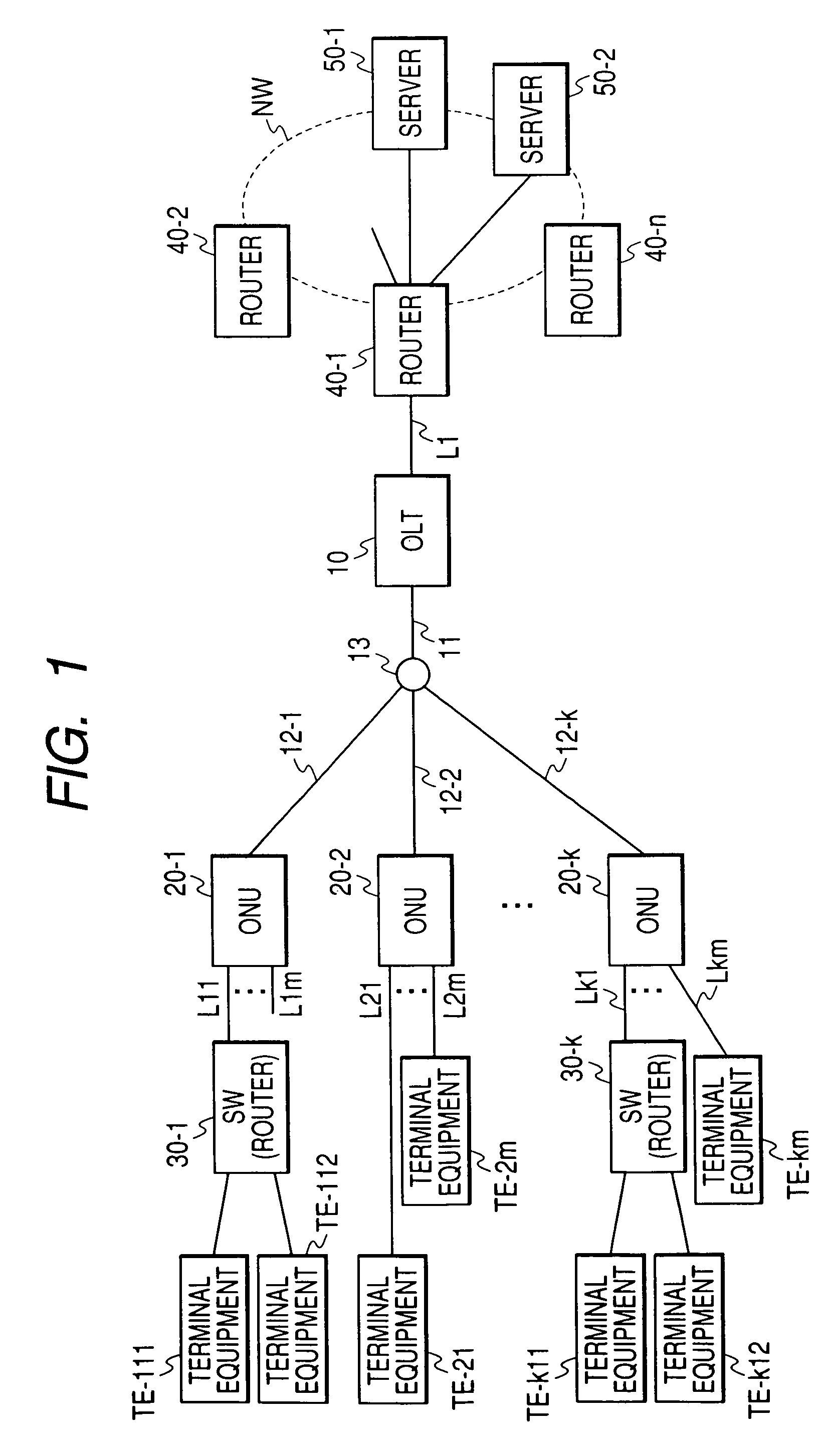
[0039]FIG. 1 is a configuration diagram of a PON system according to the present invention.

[0040]A PON system includes an optical line terminal (OLT) 10, a plurality of optical network unit (ONU) 20 (20-1 through 20-k), and an optical fiber network interconnecting these elements in the PON section. The optical network in the PON section includes an optical fiber 11 connected to the OLT 10 and one or more branch optical fibers 12-i (i=1 to k) connected to each ONU 20-i, and the branch optical fiber 12-i is branched from the optical fiber 11 by an optical splitter (optical coupler) 13.

[0041]The OLT 10 is typically installed in a user line concentration station owned by a carrier or ISP (Internet Service Provider), the ONU 20-i (i=1 to k) is installed in an office or residential building or at a user's house. Although descriptions below of the embodiments assume that the G-PON (Gigabit PON) is employed as a communication protocol for the PON section, the present invention is also effec...


PUM


Abstract

A PON system capable of utilizing the bandwidth of an optical transmission channel in the PON section. In a PON system including an OLT and a plurality of ONUs, the OLT has: a downstream frame processing unit that removes at least part of the header information in a layer 2 header from a downstream frame received from a wide area network, and converts the remaining frame portion into a frame having a header specific to the PON section; and a downstream frame processing unit that extracts a downstream frame portion to be transferred to a user terminal, from a received frame from a PON, and adds the layer 2 header information deleted in the OLT.

Description

CLAIM OF PRIORITY[0001]The present application claims priority from Japanese application JP 2006-080537 filed on Mar. 23, 2006, the content of which is hereby incorporated by reference into this application.FIELD OF THE INVENTION[0002]The present invention relates to a Passive Optical Network (PON) system, and more specifically to a PON system that allows effective use of the transmission bandwidth of an optical transmission channel.BACKGROUND OF THE INVENTION[0003]As the Internet has become widely used and information services are provided through networks, the communication network occupies an important place in social infrastructure. With the increase in Internet access from homes and business locations of companies, faster and higher-capacity access lines are increasingly required that interconnect these communication sites and the communication stations of carrier networks.[0004]As one of the access networks to be connected to a wide area network such as the Internet, there is ...

Claims


Application Information

Patent Timeline
Patent Type & Authority Patents(United States)
IPC IPC(8): H04J3/16H04J3/22H04B10/27H04B10/272H04L12/44
CPCH04Q11/0067H04Q2011/0064
Inventor MIZUTANI, MASAHIKOSHIBATA, TAKESHIKAZAWA, TOHRUASHI, YOSHIHIROKOBAYASHI, MASANOBUENDO, HIDEKI
Owner HITACHI LTD
Why Eureka
Try Eureka