Method for manufacturing an endovascular graft section

a technology of endovascular grafts and manufacturing methods, which is applied in the direction of prosthesis, blood vessels, other domestic articles, etc., can solve the problems of perioperative and postoperative morbidity and mortality, difficult and expensive manufacturing of endovascular grafts, and significant risks associated with surgical repair (including myocardial infarction and other complications related to coronary artery disease). to achieve the effect of facilitating adhesion

Inactive Publication Date: 2010-03-16
TRIVASCULAR2
View PDF267 Cites 42 Cited by
  • Summary
  • Abstract
  • Description
  • Claims
  • Application Information

AI Technical Summary

Benefits of technology

[0014]In one embodiment, melt-processible materials can be disposed on or adjacent the expandable member and first layer of fusible material prior to placing the additional layer of fusible material onto the first layer. Use of such a material (e.g., FEP, PFA, etc.) can facilitate adhesion between the layers of fusible material and serves a strain relief function for any dynamic interaction between the expandable member and the endovascular graft section made from the layers of fusible material. In some embodiments, the expandable member can be a connector ring which is configured to be secured to an expandable stent. The expandable member can also be an expandable stent or the like.

Problems solved by technology

Although improvements in surgical and anesthetic techniques have reduced perioperative and postoperative morbidity and mortality, significant risks associated with surgical repair (including myocardial infarction and other complications related to coronary artery disease) still remain.
However, manufacturing a graft from ePTFE can be difficult and expensive.
For example, it is difficult to bond ePTFE with conventional methods such as adhesives, etc.
Grafts are generally deployed in arterial systems whose environments are dynamic and which subject the devices to significant flexing and changing fluid pressure flow.
Stresses are generated that are cyclic and potentially destructive to interface points of grafts, particularly interface between soft and relatively hard or high strength materials.

Method used


Image

  • Method for manufacturing an endovascular graft section
  • Method for manufacturing an endovascular graft section
  • Method for manufacturing an endovascular graft section

Examples


Embodiment Construction

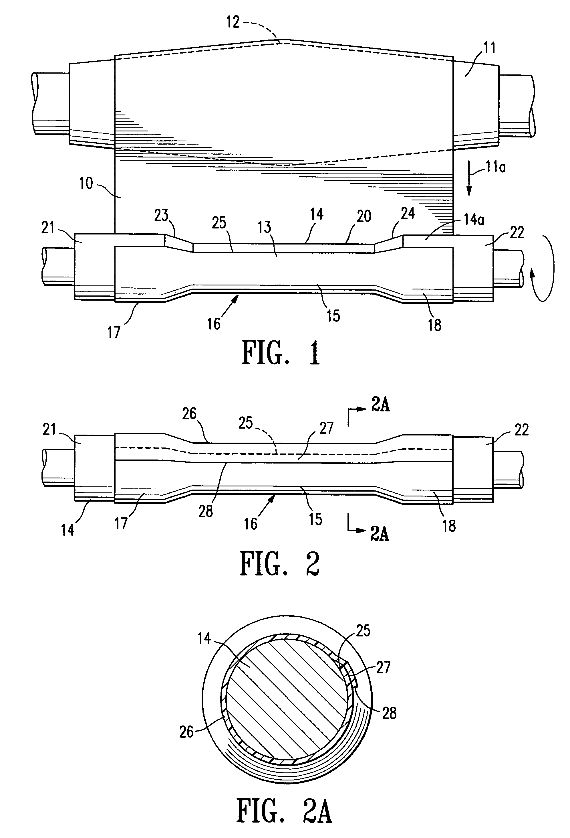
[0050]FIG. 1 illustrates a sheet of fusible material 10 stored on an elongate drum 11. The drum 11 is rotatable, substantially circular in transverse cross section and has a transverse dimension in the longitudinal center 12 that is greater than the transverse dimension of either end of the drum. The sheet of fusible material 10 is being rolled from the elongate drum in a single layer 13 onto an interior surface support means in the form of a cylindrical or tapered (conical) shape forming member or mandrel 14 to form a body section 15 of an endovascular graft 16. The body section 15 has a proximal end 17 and a distal end 18. For the purposes of this application, with reference to endovascular graft devices, the proximal end 17 describes the end of the graft that will be oriented towards the oncoming flow of bodily fluid, usually blood, when the device is deployed within a conduit of a patient's body. The distal end 18 of the graft is the end opposite the proximal end.

[0051]A single ...


PUM

PropertyMeasurementUnit
temperatureaaaaaaaaaa
pressureaaaaaaaaaa
thicknessaaaaaaaaaa

Abstract

A device and method for the manufacture of medical devices, specifically, endovascular grafts, or sections thereof. Layers of fusible material are disposed upon a shape forming member and seams formed between the layers in a configuration that can produce inflatable channels in desired portions of the graft. After creation of the seams, the fusible material of the inflatable channels may be fixed while the channels are in an expanded state. A five axis robotic seam forming apparatus may be used to create the seams in the layers of fusible material.

Description

CROSS-REFERENCE TO RELATED APPLICATIONS[0001]This application is a divisional of U.S. application Ser. No. 10 / 029,557, filed Dec. 20, 2001, now U.S. Pat. No. 7,125,464 the contents of which are incorporated herein by reference.RELATED TECHNOLOGY APPLICATIONS[0002]This application is related to U.S. patent application Ser. No. 10 / 029,570, filed Dec. 20, 2001, entitled “Method and Apparatus for Shape Forming Endovascular Graft Material”, by Chobotov, et al., now U.S. Pat. No. 6,776,604; U.S. patent application Ser. No. 10 / 029,584, filed Dec. 20, 2001, entitled “Endovascular Graft Joint and Method for Manufacture”, by Chobotov et al., now U.S. Pat. No. 7,090,693; and U.S. patent application Ser. No. 10 / 029,559, filed Dec. 20, 2001, entitled “Advanced Endovascular Graft”, by Chobotov et al. All of the above applications are commonly owned and were filed on the same date. All of the above applications are hereby incorporated by reference, each in their entirety.BACKGROUND[0003]Embodiment...

Claims


Application Information

Patent Timeline
Patent Type & Authority Patents(United States)
IPC IPC(8): A61F2/06A61F2/00A61F2/02A61F2/07A61F2/89B29C53/42B29C53/44B29C65/00B29C65/18B29C65/48
CPCA61F2/07B29C53/44B29C65/18B29C65/48B29C65/4815B29C66/1122B29C66/43B29C66/65B29C66/81422B29C66/919B29C66/929B29C66/91933B29C66/91445B29C66/9261B29C66/9241B29C66/91411B29C66/91421B29C66/4322B29C66/438B29C66/836B29C65/00Y10T156/1036A61F2250/0039B29C53/42B29C66/24B29C66/863B29K2027/18B29L2022/02B29L2022/022B29L2031/7534B29L2031/7546A61F2250/0003Y10T156/1002A61F2/89A61F2002/075A61F2230/0078B29C66/81812B29C66/49B29C66/494B29C66/73711B29C66/73712B29C66/73713B29C66/71B29C66/8161B29C66/8221B29C66/8222B29C66/12261B29K2067/00B29K2023/0683
Inventor CHOBOTOV, MICHAEL V.STEPHENS, PATRICK
Owner TRIVASCULAR2
Why Eureka
Try Eureka