Single piece co-cure composite wing

a composite wing and single-piece technology, applied in sandwich constructions, fuselages, transportation and packaging, etc., can solve the problems of increasing the manufacturing cost of the wing, affecting the design of the wing, and posing difficult design problems in the design of the wing, and achieve the effect of superior performan

Inactive Publication Date: 2010-03-23
SPECTRUM AERONAUTICAL
View PDF45 Cites 42 Cited by
  • Summary
  • Abstract
  • Description
  • Claims
  • Application Information

AI Technical Summary

Benefits of technology

[0024]An embodiment of a single piece co-cured composite structure that may be made by this method may include a composite skin having an inner skin and an outer skin, a composite frame, and a composite stringer. This structure may be a fuselage for aircraft or other structure that is enhanced by lighter weight, superior strength and durability over prior art structures. The frame and the stringer extend inward from the outer skin. The outer skin may be a flying surface and help to provide lift to the structure as it moves through the air. Additionally, the outer skin may be shaped to lessen the drag from air passing over the outer skin.
[0032]Each spar of the plurality of spars includes a spar cap and a webbing. The spar cap allows the spar to be interwoven with the flying surface. The spar cap extends parallel to the outer skin and between the outer skin and the inner skin. The inner skin may also partially extend onto the webbing of the spar to better secure the spar to the skin.
[0035]Interwoven single piece co-cured composite structures provide superior performance to structures that include pieces that are adhered together by adhesives or attached by cured resin only. For example, an interwoven skin and frame may have an interface strength three times as great as the interface strength between a frame and skin that is attached by adhesives or resin alone. Additionally, the shear-ply material of the frames and stringers provide additional protection to core fibers so that the interwoven single piece composite structures may be able to function for longer periods of time.

Problems solved by technology

The design of aircraft wings poses difficult design problems.
Furthermore, many aircraft wings also serve as a fuel tank, which adds complexity to the design of the wing.
The process of creating thousands of holes in the wing and inserting thousands of rivets in the holes substantially increases the manufacturing cost of the wing.
Additionally each hole in the wing weakens the flying surface and the structural members.
Furthermore, by increasing the number of parts for a wing, the chances of introducing a defective part are correspondingly increased.
Another drawback to current wing designs is the weight increase caused by the numerous fasteners and bulky metal structural members.
Unfortunately, there are several drawbacks to composite materials.
First, composite materials are very expensive.
This high cost is a result of the cost of the raw materials as well as the cost of manufacturing the composite parts from the raw material.
The high manufacturing costs of the composite structures combined with the price of the expensive raw materials, often makes the use of composite materials cost prohibitive.
Another drawback to composite materials is the assembling of the composite material.
Placing holes in composite materials for attachment of fasteners severs the strands of fibers within the material and creates weak points within the material.
While forming holes in the composite material by displacing the strands of the uncured fiber prevents severing of the fibers, this process is time-consuming and often impractical.
However, the distribution of the epoxy and the placement of the parts together can require expensive machines and numerous jigs.
Thus, the construction of the wing has implications not only on the initial cost of the wing, but also implications on the maintenance costs through the life of the wing.

Method used


Image

  • Single piece co-cure composite wing
  • Single piece co-cure composite wing
  • Single piece co-cure composite wing

Examples


Embodiment Construction

[0047]The preferred embodiments of the invention are now described with reference to FIGS. 1-9C, where like reference numbers indicate identical or functionally similar elements. The members of the present invention, as generally described and illustrated in the figures, may be implemented in a wide variety of configurations. Thus, the following more detailed description of the embodiments of the system and method of the present invention, as represented in the Figures, is not intended to limit the scope of the invention as claimed, but is merely representative of presently preferred embodiments of the invention.

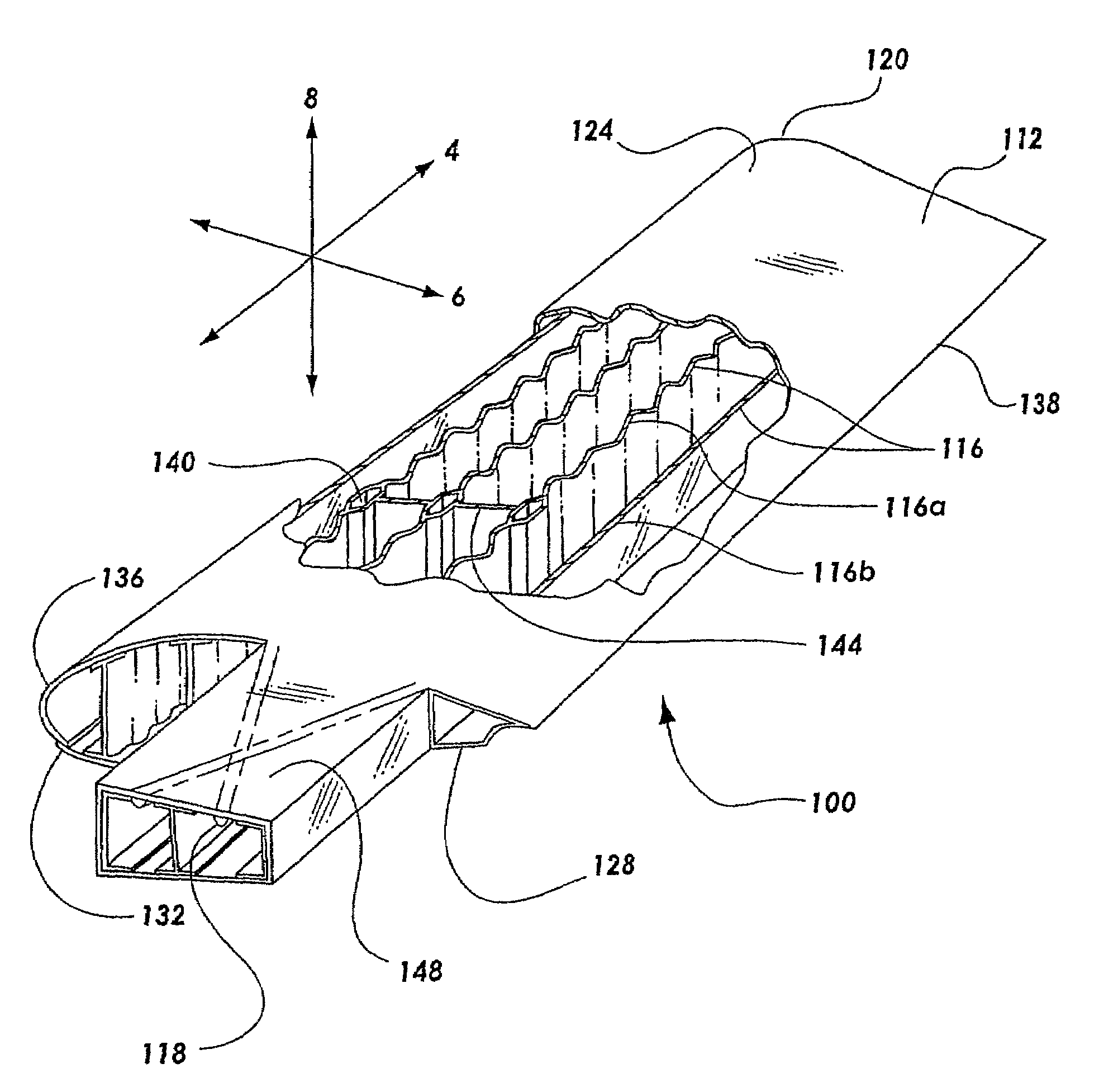
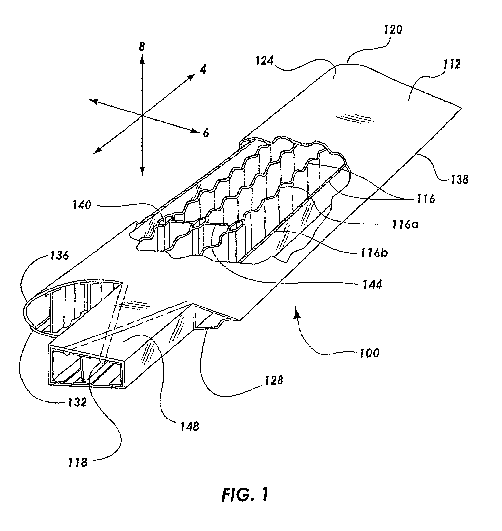
[0048]The present invention provides for a single piece co-cured composite wing structure. Referring to FIG. 1, a single piece co-cured wing 100 having a composite flying surface 112 and a plurality of composite structural members is illustrated. The composite structural members may have various embodiments for maintaining the general shape of the flying surface 112 and allo...


PUM

PropertyMeasurementUnit
pressureaaaaaaaaaa
pressureaaaaaaaaaa
pressuresaaaaaaaaaa

Abstract

A single piece co-cured composite wing is disclosed. The wing has a flying surface and structural members. In one embodiment the structural members may be a plurality of spars. The spars may have various shapes to increase the buckling strength. The spars may be wave shaped, such as a sinusoidal shape. The flying surface and the structural members are co-cured in order to form a single piece, integral wing structure. A process for manufacturing a single piece co-cured wing is also disclosed. The process may include laying out composite sheets for the flying surface of the wing. Then, the composite material of the spars is arranged around a plurality of pressurizable forms. Finally, the composite material is cured in a clamshell frame. A single piece co-cured composite structure is also disclosed that includes an outer skin, and inner skin, a frame, and a stringer.

Description

CROSS-REFERENCED RELATED APPLICATIONS[0001]This application is a continuation-in-part of prior application Ser. No. 10 / 726,970, filed Dec. 3, 2003 now U.S. Pat. No. 7,445,744, which is a divisional application of application Ser. No. 10 / 175,722 filed Jun. 20, 2002, now issued as U.S. Pat. No. 6,889,937, which is a continuation-in-part of application Ser. No. 09 / 443,227 filed Nov. 18, 1999, now issued as U.S. Pat. No. 6,482,497 to Craig B. Simpson, Mike G. Allman, Steven T. Tuttle, and Larry J. Ashton.BACKGROUND OF THE INVENTION[0002]1. Field of the Invention[0003]The present invention relates to a wing structure. More particularly, the present invention relates to a single piece composite wing structure.[0004]2. Technical Background[0005]The design of aircraft wings poses difficult design problems. Multiple factors must be balanced in order to design an effective wing. One consideration is the shape of the wing. The wing must have the proper airfoil-shape in order to create the desi...

Claims


Application Information

Patent Timeline
Patent Type & Authority Patents(United States)
IPC IPC(8): B64C1/00
CPCB64C3/20Y10T428/24124Y10T428/24612Y10T428/24107
Inventor SIMPSON, CRAIG B.ASHTON, LARRY J.ALLMAN, MIKE G.TUTTLE, STEVEN T.
Owner SPECTRUM AERONAUTICAL
Why Eureka
Try Eureka