Microfluidic assay devices
a technology of microfluidic assay and assay device, which is applied in the direction of laboratory glassware, gas-gas reaction process, furnace, etc., can solve the problems of inability to meet the data acquisition or reaction time, the flow rate through the device may be too fast to handle the data acquisition or the effect of the necessary reaction tim
- Summary
- Abstract
- Description
- Claims
- Application Information
AI Technical Summary
Benefits of technology
Problems solved by technology
Method used
Image
Examples
example 1
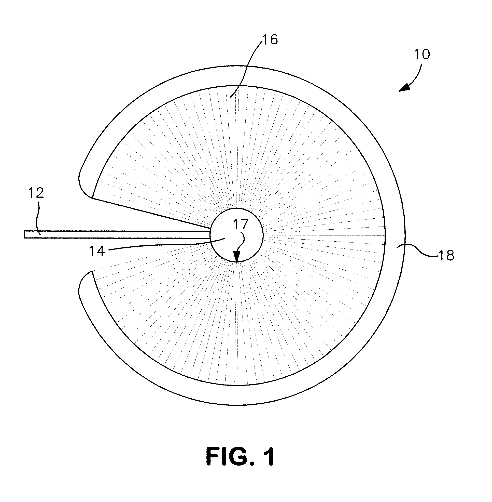
[0058]The ability to form a microfluidic device in accordance with one embodiment of the present invention was demonstrated. Specifically, a micromolded polymer sheet was initially formed from polydimethylsiloxane (PDMS) silicone rubber (“Sylgard 184”, available from Dow Corning of Midland, Mich.). The PDMS prepolymer was a liquid having a viscosity of 3900 centipoise. The PDMS prepolymer was polymerized with a radical-mediated mechanism that employed a platinum-based catalyst (1 part catalyst: 10 parts prepolymer). The initial liquid properties of the PDMS allowed it to replicate finely structured molds with high fidelity and good dimensional stability.
[0059]A 50-micrometer thick photoresist (available from Dow Chemical under the name “EPON SU-8”) was then formed on a silicon wafer. Specifically, 3 milliliters of the SU-8 photoresist was dispensed at 100 RPM onto a 6″ diameter silicon wafer, ramped slowly to 500 RPM, and then ramped quickly to 2000 RPM and held for 30 seconds. The ...
example 2
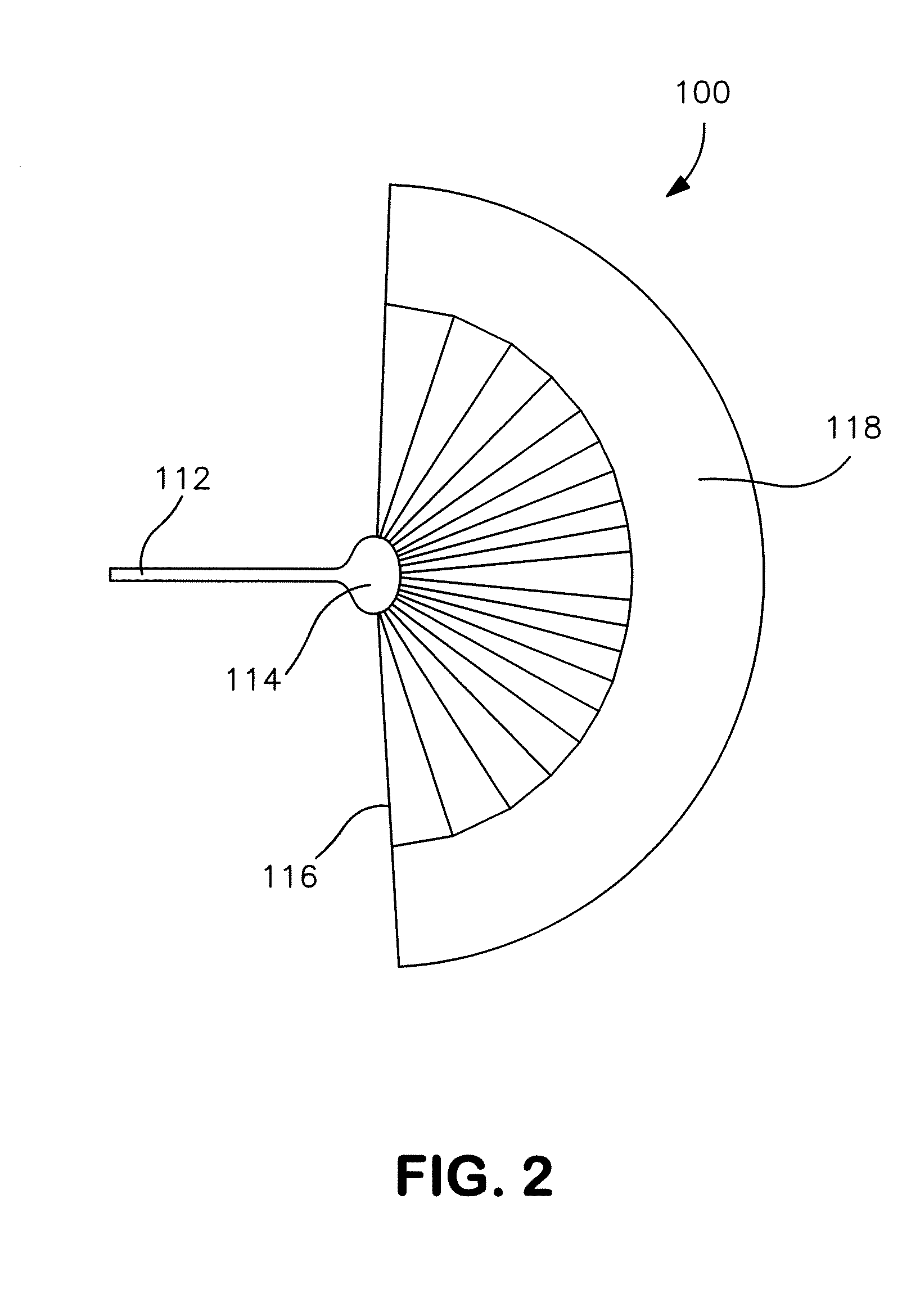
[0064]A microfluidic device was formed as described in Example 1, except that the design utilized is shown in FIG. 2 and had the following dimensions.
[0065]
TABLE 2Dimensions of the Fluidic ZonesVolumeWidthDepthAspect(nanoliters)(micrometers)(micrometers)RatioInput Channel165400508Analysis Zone2603000 (max)5060Wicking45050501Channels(20×)Overflow Zone924022005044TOTAL10,115
example 3
[0066]A microfluidic device was formed as described in Example 1, except that the design utilized is shown in FIG. 3 and had the following dimensions.
[0067]
TABLE 3Dimensions of the Fluidic ZonesVolumeWidthDepthAspect(nanoliters)(micrometers)(micrometers)RatioInput Channel165400508Analysis Zone2402000 (max)5050Wicking45050501Channels(20×)Overflow Zone924022005044TOTAL10,095
PUM
| Property | Measurement | Unit |
|---|---|---|
| cross-sectional area | aaaaa | aaaaa |
| aspect ratio | aaaaa | aaaaa |
| aspect ratio | aaaaa | aaaaa |
Abstract
Description
Claims
Application Information
 - R&D
- Intellectual Property
- Life Sciences
- Materials
- Tech Scout
- Unparalleled Data Quality
- Higher Quality Content
- 60% Fewer Hallucinations
Browse by: Latest US Patents, China's latest patents, Technical Efficacy Thesaurus, Application Domain, Technology Topic, Popular Technical Reports.
© 2025 PatSnap. All rights reserved.Legal|Privacy policy|Modern Slavery Act Transparency Statement|Sitemap|About US| Contact US: help@patsnap.com


