
Catheter with variable magnetic field generator for catheter guidance in a subject

a variable magnetic field and catheter guidance technology, applied in the field of catheters, can solve the problems of difficult movement, difficulty, and difficulty of field generation devices, and achieve the effects of avoiding insertion, avoiding insertion, and avoiding insertion

Inactive Publication Date: 2010-03-30
SIEMENS HEALTHCARE GMBH
View PDF48 Cites 102 Cited by
  • Summary
  • Abstract
  • Description
  • Claims
  • Application Information

AI Technical Summary

Benefits of technology

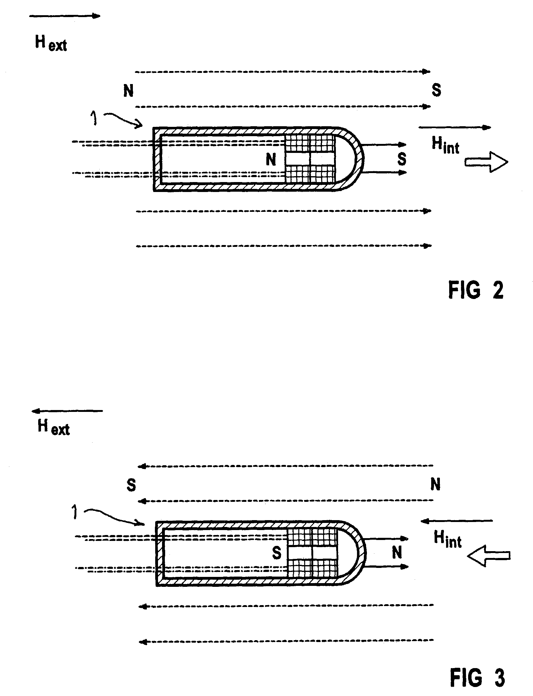
[0017]The magnetic field generated at the catheter is not fixed or unalterable, but can be varied in terms of field strength or field direction as needed. This creates the possibility, for example, of increasing the field strength as needed, so that the above-cited problems as to a non-optimum coupling to the external field can be overcome. Moreover, there is the possibility of varying the field direction. It is possible to vary the field direction, as needed, of not only the external field but also the field of the inner magnetic element. As a result, it is possible by means of designated variation of the catheter's magnetic field and a designated variation of the external magnetic field to influence the interaction of the two and thus to be able to utilize and vary the coupling effect on the catheter tip that arises from the interaction of the two fields, and is expressed in directed interaction forces on the catheter tip. As a result, differently directed forces can be exerted on the catheter tip. This enables a simpler navigation and movement of the catheter in the patient.
[0023]It is expedient to provide an ultrasound generating and image pickup device is provided in the region of the catheter tip, so the catheter includes not only the magnetic motion and guidance device in the tip but also the image generating and pickup device. Employment of the magnetic guidance and positioning system, offers the possibility of being able to position and navigate the catheter exactly in view of the diseased body region as well as being able to make ultrasound images thereof. X-ray monitoring, as is conventionally employed, does not allow an image presentation of the vessel wall but only of the vessel volume. The augmentation of monitoring with evaluation of the ultrasound images, allows the vessel wall itself to be seen.

Problems solved by technology

A disadvantage, however, is that this field-generating device is very heavy and is thus somewhat difficult to move.
Difficulties arise due the cumbersome nature of the device particularly when the catheter is to be moved around a vessel bend, where it encounters greater resistance and is prone to become lodged.
A further disadvantage is that, due to the employment of a permanent magnet in the catheter, the magnetic coupling between its magnetic field and the external magnetic field may not be strong enough in order to overcome the aforementioned resistance, for example because the external magnetic field is somewhat attenuated in the region where the magnetic tip of the catheter is located.
The aforementioned problems in the manual movement of the catheter by a physician thus continue to exist.

Method used


Image

  • Catheter with variable magnetic field generator for catheter guidance in a subject
  • Catheter with variable magnetic field generator for catheter guidance in a subject
  • Catheter with variable magnetic field generator for catheter guidance in a subject

Examples


Embodiment Construction

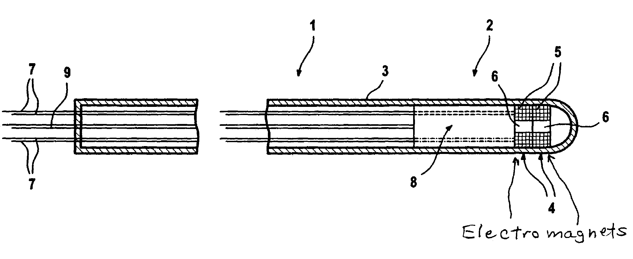
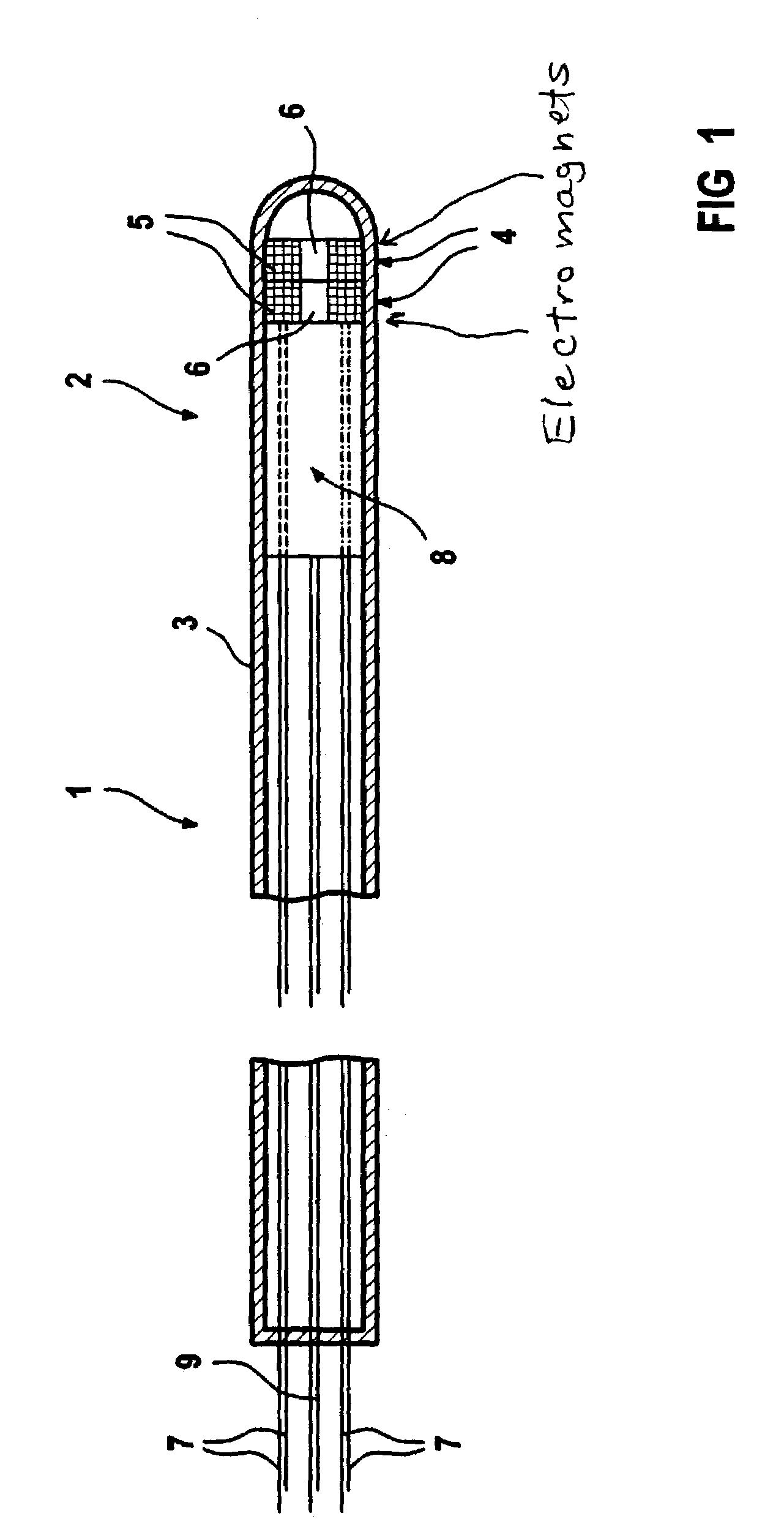
[0027]FIG. 1 shows the inventive catheter 1 with a tip 2 at which two electromagnets 4 are positioned at fixed locations in the inside of the catheter envelope 3 in the illustrated example. Each electromagnet 4 is composed of a coil 5 and a core 6, for example an iron core. Separate leads 7 are provided in the inside of the catheter envelope, these being conducted toward the outside. The respective coils 5 of the electromagnets 4 are able to be separately supplied with current via the leads 7.

[0028]An ultrasound system 8 for generating ultrasound and for picking up ultrasound images is also provided in the region of the catheter tip 2, the supply and signal lines thereof likewise being conducted toward the outside in the catheter envelope 3.

[0029]FIGS. 2 and 3 show the possibility of moving the catheter contact-free in the inside of the body using an external magnetic field that interacts with the magnetic field generated with the electromagnets 4. In FIG. 2, an external magnetic fi...


PUM


Abstract

A catheter, particularly an intra-vascular catheter, has at least one magnetic field-generating element arranged in the catheter envelope in the region of the catheter tip, characterized in that the magnetic field of which is variable while the catheter is inserted into a patient.

Description

BACKGROUND OF THE INVENTION[0001]1. Field of the Invention[0002]The present invention is directed to a catheter, particularly an intra-vascular catheter, having at least one magnetic field-generating element arranged in the catheter envelope in the region of the catheter tip.[0003]2. Description of the Prior Art[0004]A catheter is an elongated instrument that, for example, is inserted into a vessel track of the human or animal body up to a certain point. For example, such catheters are utilized in the framework of treating diseases of the arterial coronary vessels that cause a cardiac infarction. In the case of arteriosclerosis, deposits (arteriosclerotic plaque) occur at the vessel wall and thus lead to a “plugging” of one or more coronary vessels. By employment of a catheter, the diseased vessel regions can be reached and treatment activity can be undertaken.[0005]For moving and guiding the catheter inserted into the vessel, it is known to employ an externally generated magnetic f...

Claims


Application Information

Patent Timeline
IPC IPC(8): A61B6/00A61B8/00A61B34/00A61M25/01A61M25/08
CPCA61B19/22A61M25/0127A61B2019/2253A61B34/70A61B34/73
Inventor MASCHKE, MICHAEL
Owner SIEMENS HEALTHCARE GMBH
Learn More