Internal utility meter antenna

a utility meter and antenna technology, applied in the direction of resonant antennas, separate antenna unit combinations, antenna supports/mountings, etc., can solve the problems of communication loss, incomplete data, severe impact on electrical performance, etc., and achieve optimal electrical performance

Inactive Publication Date: 2010-04-06
MOBILE MARK
View PDF4 Cites 36 Cited by
  • Summary
  • Abstract
  • Description
  • Claims
  • Application Information

AI Technical Summary

Benefits of technology

[0006]In the present invention, a one or two part dipole radiator for single band or multi-band application is provided and is located internally in the utility meter. The dipole radiator is unique in its location and shape within the utility meter, with the location and shape allowing for optimal electrical performance compared to prior art internal antennas that have been used.

Problems solved by technology

To increase mechanical reliability, in a prior art system the antenna is relocated internally, severely impacting the electrical performance.
The result has been loss of signal resulting in communication loss, incomplete data, and reduced performance.

Method used


Image

  • Internal utility meter antenna
  • Internal utility meter antenna
  • Internal utility meter antenna

Examples


Embodiment Construction

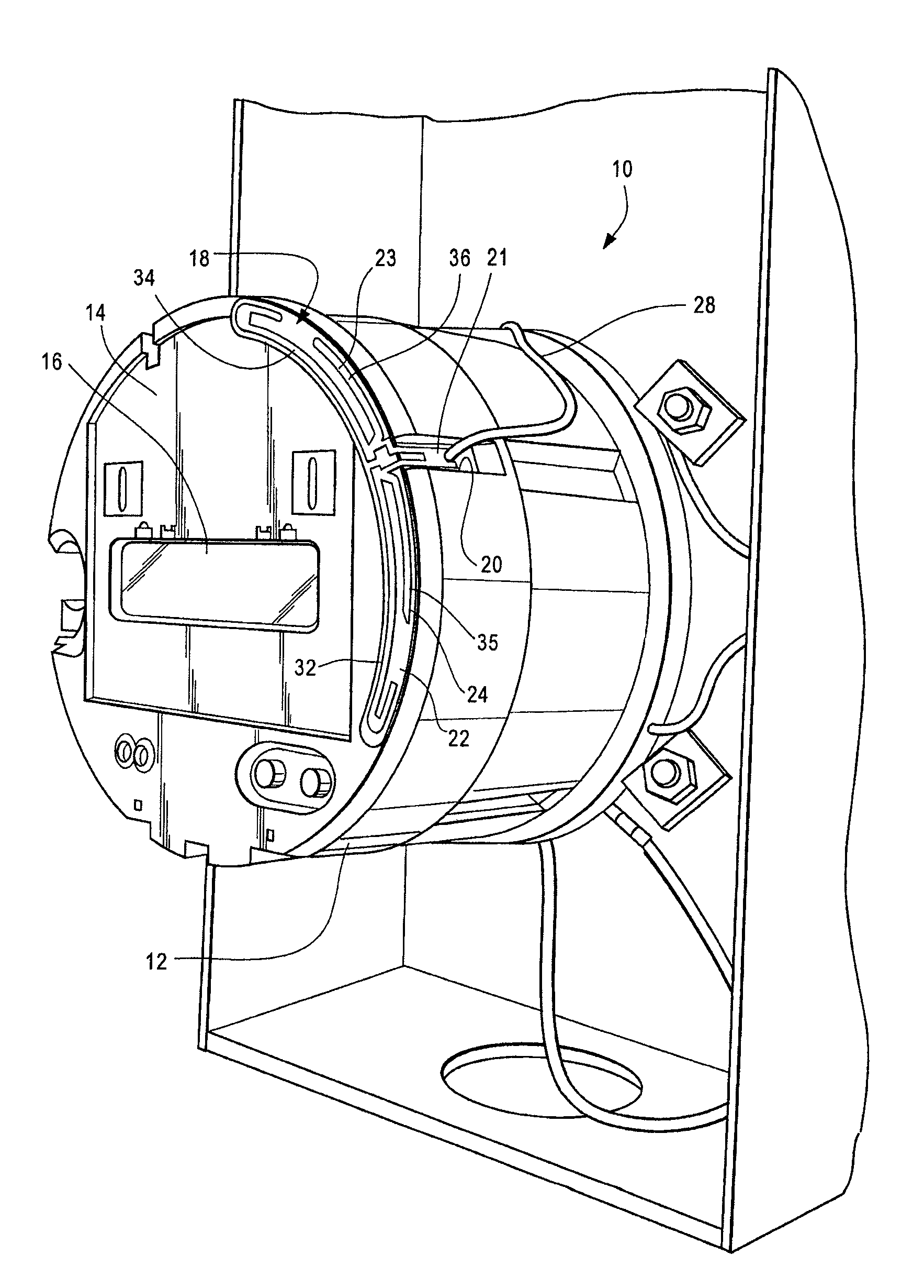
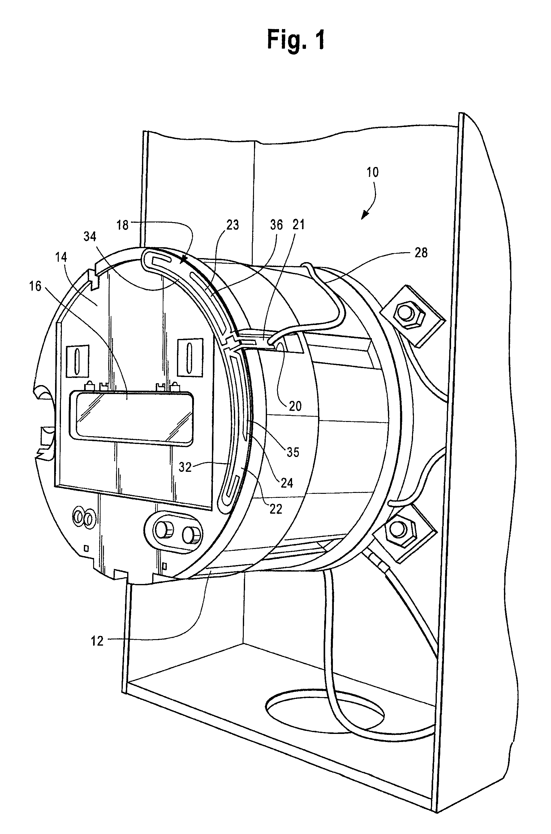
[0018]Referring to FIG. 1, a utility meter 10 is shown therein having a generally circular sidewall 12 and a front surface 14 which presents a readout 16. A transparent glass or plastic radome (not shown) covers the front surface 14 as is conventional with utility meters. The radome (protective meter cover) may be made of a dielectric material such as polycarbonate, glass, lexan, or similar dielectric materials.

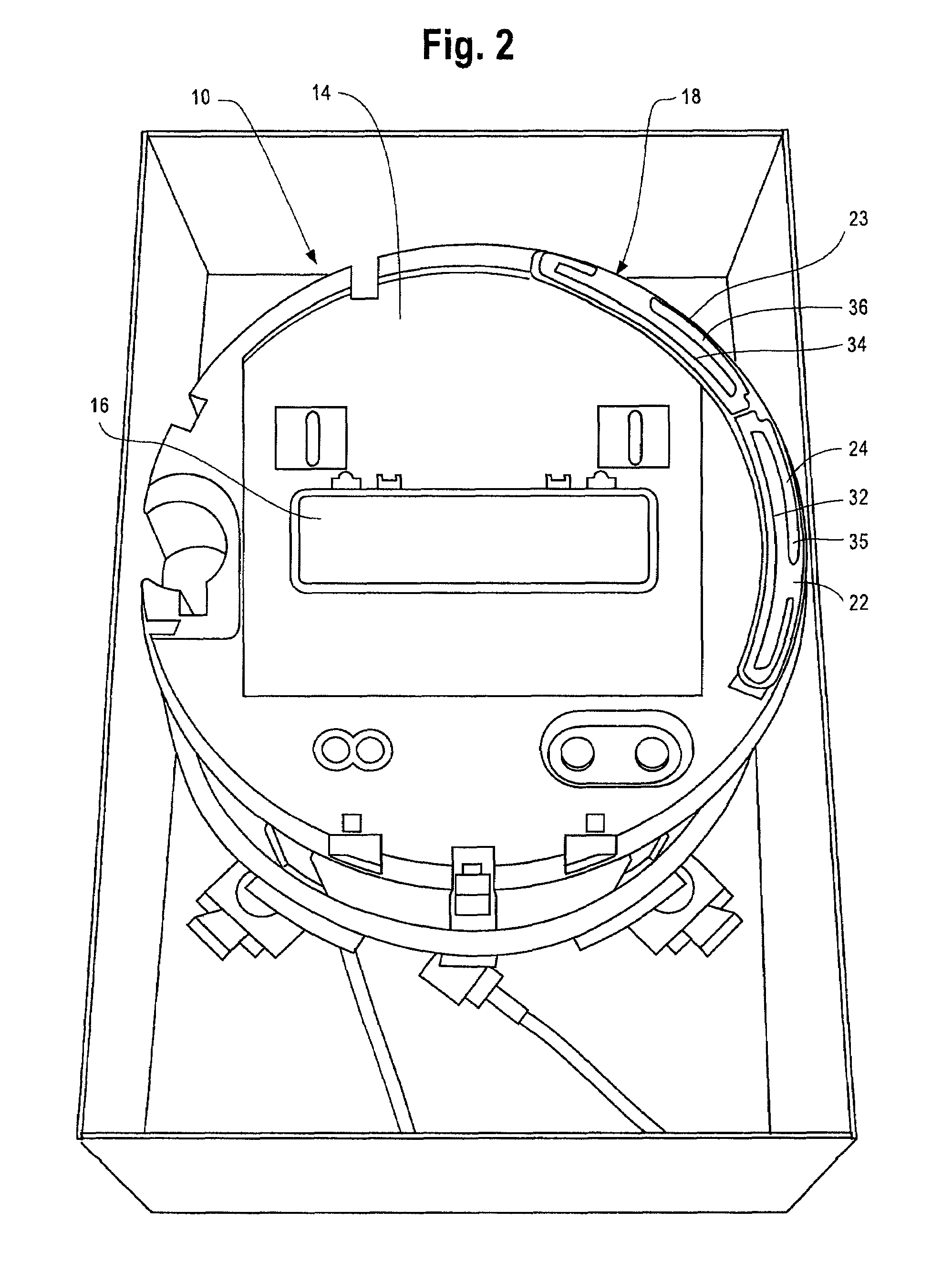
[0019]A typical meter housing used for residential and commercial use has a diameter between 4 inches and 7 inches. A dual band dipole antenna 18 is fastened to the top surface 14 of the utility meter 10. A notch 20 is defined by the sidewall 12, with the balun portion 21 of the antenna positioned within the notch 20.

[0020]I have found that the antenna radiator gives best performance when it is generally curved or contoured to the shape of the meter housing.

[0021]Referring to FIGS. 1-3, the dipole antenna 18 includes a dielectric substrate 22 and it comprises two asymmetrical...


PUM


Abstract

A utility meter has an internal antenna for transmitting data. The antenna is positioned between the radome of the utility meter and its front surface. The antenna comprises dipole radiator that is generally curved to the shape of the meter housing. The dipole radiator comprises a dielectric substrate carrying two asymmetric curved radiating metallic sheets, each forming a portion of the dipole, which combined extend about 135° of the circumference of the utility meter. A balun feed is connected to the metallic sheets and a transmission line is coupled to a transmitter.

Description

[0001]This application claims the benefit of priority to Provisional Application Ser. No. 61 / 197,069 filed Oct. 22, 2008 and incorporates herein the disclosure of the Provisional Application.I. FIELD OF THE INVENTION[0002]The present invention is in the field of remote utility meter monitoring. More particularly, the present invention is in the field of internal antenna design for utility meters to optimize electrical performance.II. BACKGROUND OF THE INVENTION[0003]Certain prior art utility meters, including residential and commercial utility meters, are fixed and rely on manual recording of services used. Other prior art utility meters use internal electronic components which read the data remotely, thus eliminating the need for an individual to manually go to each utility meter and manually record the data. In this type of prior art device, the data is transmitted via radio using an external antenna that is typically outside of the utility meter housing, for remote monitoring.[00...

Claims


Application Information

Patent Timeline
Patent Type & Authority Patents(United States)
IPC IPC(8): H01Q9/28
CPCH01Q1/2233H01Q9/26H01Q5/48H01Q5/40H01Q21/30
Inventor PAKOSZ, DANIELRAIMAN, CLIFFORD
Owner MOBILE MARK
Why Eureka
Try Eureka