Membrane based electrochemical cell stacks

a technology of electrochemical cells and membranes, applied in the field of membrane-based electrochemical cells, can solve the problems of high cost of fuel cells when compared to conventional power generation technology, deterring widespread use, and laborious, and the cost of fabricating and assembling fuel cells can be significan

Active Publication Date: 2010-04-13
SILICON VALLEY BANK
View PDF18 Cites 6 Cited by
  • Summary
  • Abstract
  • Description
  • Claims
  • Application Information

AI Technical Summary

Benefits of technology

[0027]The present invention provides notable improvements over conventional stacks and related processes, including those described above. In particular, the present invention provides improved electrochemical cassettes and fuel cell cassettes, including fuel cell stacks utilizing composite MEAs. As used herein, “composite MEA” is intended to refer to traditional laminated MEAs having an ion conductive membrane (ICM) interposed between two gas diffusion layers (GDL) which is then bonded about the periphery of the laminate with a non-porous, insulating gasket. Each sealed stack module, referred to herein as a “fuel cell cassette” or “electrochemical cassette” is an assembly of electrochemical components which has bonded internal manifolding and is sealed to form a self contained unit. These electrochemical or fuel cell cassettes may be designed to readily achieve standardized specifications.
[0028]In accordance with the present invention, sealing channels are formed in the gasket of the composite MEA. This allows for significant simplification of the other portions of the stack, particularly simplification of the non-porous separator plate. Rather than forming an edge gasket around the MEA that is flat, composite membranes are prepared which comprise a gasket that incorporates the sealing channels into the gasket of the composite MEA. A stack can subsequently be made with simple flow fields (e.g. metal screens) and flat separator plates (e.g. sheet stock) or by utilizing bipolar plate components. During the fabrication of the cassette, the sealant is introduced from the edges of the stack (or through sealant holes in the stack components). The sealant travels through the channels incorporated in the gasket of the MEA, bonding to the gasket and the separator plate.

Problems solved by technology

However, the high cost of fuel cells when compared to conventional power generation technology deters their widespread use.
The cost of fabricating and assembling fuel cells can be significant, due to the materials and labor involved.
These processes are labor intensive and not conducive to high volume manufacturing, thereby adding to the high cost of fuel cells.
Additionally, the variability of these processes results in poor manufacturing yield and poor device reliability.
Fuel cell stacks range in design depending upon power output, cooling, and other technical requirements, but may utilize a multitude of MEAs, seals, flow fields and separator plates, in intricate assemblies that result in manufacturing difficulties and further increased fuel cell costs.
These conventional means of applying compression add even more components and complexity to the stack and pose additional sealing requirements.
Other disadvantages observed in connection with some conventional fuel cell stacks are electrical in nature.
For example, depending upon the configuration of the fuel cell and the degree of exposure of the MEA to the reactants and waste streams in the various manifolds providing reagents and coolants to the flow fields, a cross-cell potential problem may arise.
In particular, if the exposure of the MEA to those reagents is significant, there may be a “shorting-out” of the MEA layer, thus resulting in poor performance of the fuel cell overall.
Also, exposure of the MEA to some potential cooling fluids can be detrimental to the membrane portion.
However, notable disadvantages have been associated with those processes.
However, assembly of that stack still requires manual alignment of the components during the adhesion process, in a manner not unlike caulking a seal, and sealing only occurs at those interfaces where adhesive has been applied through active placement.
However, this design relies on conventional sealing among the components and between subunits.
While that process may offer certain improvements to those previously described state of the art methods for forming fuel cell stacks, several deficiencies remain.
In practice, for example, the process requires high injection pressures and is associated with slow fill times. High injection pressures further require component designs that protect the more fragile components of the stack (i.e. MEA).
Another notable disadvantage is that a significantly large area of the each layer is necessarily sacrificed due to the sealing process itself.

Method used


Image

  • Membrane based electrochemical cell stacks
  • Membrane based electrochemical cell stacks
  • Membrane based electrochemical cell stacks

Examples


example 1

2 Cell Stack Performance Data

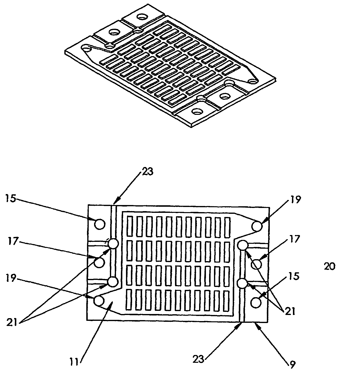
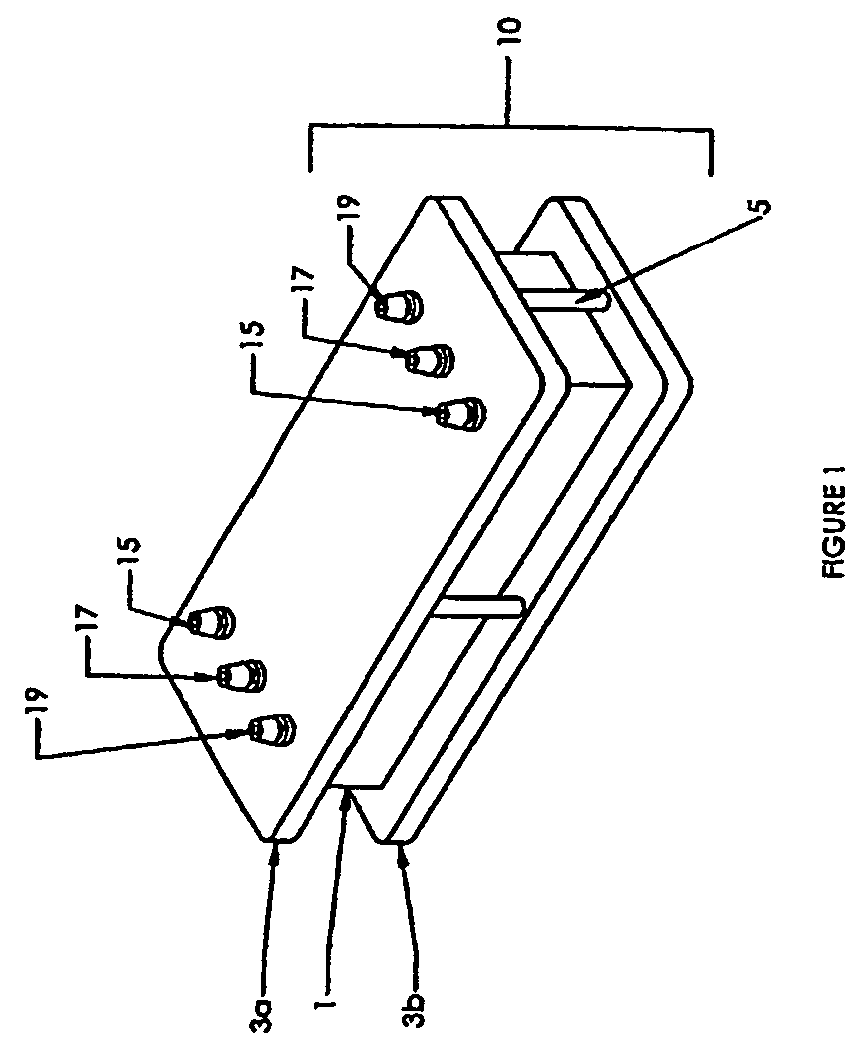
[0096]Using the ridge and raised channel pattern depicted in FIG. 7, composite MEAs depicted in FIG. 2 were molded from commercial MEAs and silicone resin using the gasket mold depicted in FIG. 3 and FIG. 4. Separator plates were cut from plate stainless steel and flow fields were cut from stainless steel mesh. Each component is depicted in FIG. 10, e.g., two composite MEAs, four flow field screens, one separator plate, and two end plates were assembled in the mold in the following order: end plate, flow field screen, composite MEA, flow field screen, separator plate, flow field screen, composite MEA, flow field screen, and end plate. The assembly was encapsulated with the silicone resin, Silastic, (available commercially from The Dow Corning Corporation of Midland, Mich., USA) by pushing the resin into the sealant holes with a hand dispenser.

[0097]Table 1 shows total voltage, cell voltage, current and current density for the fuel stack assembly above de...

example 2

Standard Injection Molding

[0099]Few changes would be made in the above described scheme to employ automated injection molding. With the use of two part resins (e.g., the silicone used in Example 1), we have shown that the resin can be injected into the channels by a diving pressure rather than pulling a vacuum on the internal ports. For traditional injection molding of a thermoplastic resin, the mold used would have to accommodate the temperature and pressure associated. Molten resin would be injected into the injection holes and around the edges of the assembly, allowed to cool and harden. Injection velocity profile, pack pressure, and cooling time would be optimized to minimize the possibility of component damage as well as to control shrinkage / warpage ensuring sealing of the final part. Lastly, the fuel cell cassette would be removed from the mold.


PUM

PropertyMeasurementUnit
viscosityaaaaaaaaaa
viscosityaaaaaaaaaa
viscosityaaaaaaaaaa

Abstract

The present invention provides membrane cassettes and stacks thereof which are suitable for a use in a variety of electrochemical applications. The invention further provides membrane cassettes which comprise one or more composite membrane electrode assemblies which have a peripheral gasket where the gasket has at least one groove or channel for introducing and distributing a sealant about the cassette. In certain preferred embodiments, the invention provides cassettes and stacks which are suitable for use in fuel cell applications.

Description

[0001]The present application is a 371 of International Application No. PCT / US03 / 37127, filed on Nov. 18, 2003, which claims the benefit of U.S. Provisional Application No. 60 / 427,261, filed on Nov. 18, 2002.FIELD OF INVENTION[0002]This invention relates to membrane-based electrochemical cells, and more particularly, to proton exchange membrane (PEM) fuel cell stacks. The present invention also describes novel processes for producing these PEM fuel cell stacks.BACKGROUND OF THE INVENTION[0003]Membrane based electrochemical cells, and particularly, proton exchange membrane (PEM) fuel cells are well known. PEM fuel cells convert chemical energy to electrical power with virtually no environmental emissions and differ from a battery in that energy is not stored, but derived from supplied fuel. Therefore, a fuel cell is not tied to a charge / discharge cycle and can maintain a specific power output as long as fuel is continuously supplied. The large investments into fuel cell research and ...

Claims


Application Information

Patent Timeline
Patent Type & Authority Patents(United States)
IPC IPC(8): H01M2/08H01M2/14H01M8/02H01M8/04H01M8/10H01M8/24
CPCH01M8/0258H01M8/0267H01M8/0273H01M8/0276H01M8/0284H01M8/0286H01M8/04007H01M8/2485H01M8/0297Y02E60/50H01M8/242H01M8/248H01M2008/1095H01M8/2483H01M8/2457H01M8/0263H01M8/026
Inventor SABIN, PAULREZAC, PETEROSENAR, PAULENAYETULLAH, MOHAMMAD
Owner SILICON VALLEY BANK
Why Eureka
Try Eureka