Single clock driven shift register and driving method for same

a shift register and single clock technology, applied in the field of single clock driven shift registers, can solve the problems of overlap affecting the precision of sampling and image quality, and achieve the effect of reducing the number of times the clock is pressed

Active Publication Date: 2010-04-13
AU OPTRONICS CORP
View PDF3 Cites 7 Cited by
  • Summary
  • Abstract
  • Description
  • Claims
  • Application Information

AI Technical Summary

Problems solved by technology

The overlap affects the precision of the sampling and the image quality seriously.

Method used


Image

  • Single clock driven shift register and driving method for same
  • Single clock driven shift register and driving method for same
  • Single clock driven shift register and driving method for same

Examples


Embodiment Construction

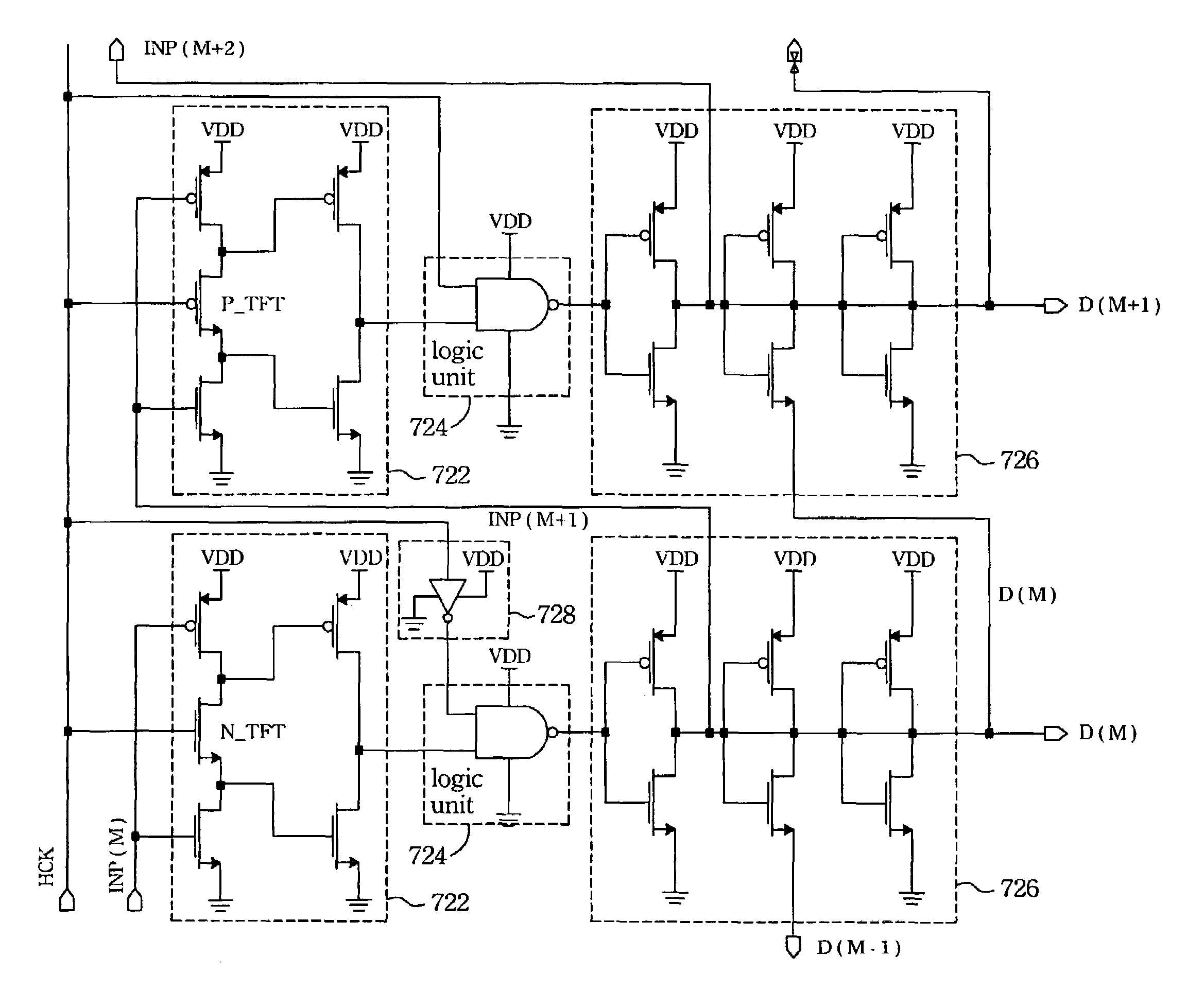
[0025]FIG. 5 is a block diagram of a preferred embodiment of a driving system according to this invention. As shown, the driving system 50 comprises a controller 60, a source driver 70 and a scan driver 80. The controller 60 generates a display data D, a horizontal clock signal HCK and a horizontal start signal HST to input to the source driver 70 and also generates a vertical clock signal VCK and a vertical start signal VST to input to the scan driver 80 at the same time. The source driver 70 comprises a single clock driven shift register 72 and a plurality of sampling gates 74, wherein each of sampling gates 74 corresponds to one column of the pixel array (not shown) on the display panel. The horizontal clock signal HCK and the horizontal start signal HST from the controller 60 are input to the single clock driven shift register 72 in order to generate the sampling signals Sa. The sampling signals Sa will be input to each of sampling gates 74 in order. The sampling gate 74 receive...


PUM


Abstract

A single clock driven shift register comprising multiple stages is provided. The (M)th stage comprises a latch unit, a logic unit, and a non-overlap buffer. The latch unit latches an input signal from the (M−1)th stage according to a clock signal. The logic unit connecting to an output terminal of the latch unit deals with an output signal of the latch unit and the clock signal with an NAND logic calculation. The non-overlap buffer connecting to the output terminal of the logic unit comprises at least three inverters connected in a serial, and an output signal of the first inverter coupled to the output terminal of the logic unit is input to an latch unit of the (M+1)th stage. Meanwhile, an output signal of the non-overlap buffer of the (M−1)th stage is input to the non-overlap buffer or the logic unit to delay the output signal of the non-overlap buffer.

Description

FIELD OF THE INVENTION[0001]This invention relates generally to a single clock driven shift register utilized in a display driving circuit, more particularly, it relates to a single clock driven shift register capable of improving the output signal overlap of itself.DESCRIPTION OF THE RELATED ART[0002]Based on the requirements of lightness, thinness, and non-radiation, LCD replaces CRT gradually. It is utilized in electronic products, such as desk computer, PDA, notebook computer, digital camera and cellular telephone etc.[0003]In order to display images, we perform electric field to control the transmittance of the liquid crystal in Active Matrix Liquid Crystal Display (AMLCD). As indicated in FIG. 1A, a typical AMLCD 10 comprises a LCD panel 20 and a driving system 30. The LCD panel 20 has a pixel array 22 on it. The driving system 30 comprises a controller 32, a source driver 34 and a scan driver 36. Each pixel unit 122 in the pixel array 22 connects with a thin film transistor (...

Claims


Application Information

Patent Timeline
Patent Type & Authority Patents(United States)
IPC IPC(8): G09G3/36G09G3/00G11C8/00G11C19/00G11C19/28
CPCG11C19/28G11C19/00G09G3/3674G09G3/3685
Inventor TSENG, JUNG-CHUNLIU, SHENG-CHAOYU, JIAN-SHEN
Owner AU OPTRONICS CORP
Why Eureka
Try Eureka