Control of artificial lighting of a scene to reduce effects of motion in the scene on an image being acquired

a technology of artificial lighting and scene, which is applied in the field of automatic exposure control of digital cameras, can solve the problems of reduced depth of field and increased optical blur, increased noise within the image, and difficulty for users to hold a camera by hand during an exposure without imparting some degree, so as to reduce or eliminate motion blur in the image, improve the quality of the captured image, and reduce the effect of motion blur in the resulting imag

Active Publication Date: 2010-04-13
QUALCOMM INC
View PDF18 Cites 19 Cited by
  • Summary
  • Abstract
  • Description
  • Claims
  • Application Information

AI Technical Summary

Benefits of technology

[0004]The data acquired by the image sensor are typically processed to compensate for imperfections of the camera and to generally improve the quality of the image obtainable from the data. The correction for any defective pixel photodetector elements of the sensor is one processing function. Another is white balance correction wherein the relative magnitudes of different pixels of the primary colors are set to represent white. This processing also includes de-mosaicing the individual pixel data to superimpose data from spatially separate monochromatic pixel detectors of the sensor to render superimposed multi-colored pixels in the image data. This de-mosaicing then makes it desirable to process the data to enhance and smooth edges of the image. Compensation of the image data for noise and variations of the camera optical system across the image and for variations among the sensor photodetectors is also typically performed within the camera. Other processing typically includes one or more of gamma correction, contrast stretching, chrominance filtering and the like.
[0015]The improved techniques of controlling exposure and / or artificial light parameters are also preferred over other ways that have been used or suggested for minimizing or eliminating motion blur in the image. An extremely short duration electronic strobe flash can be used to effectively stop any image motion so long as the exposure duration is limited to substantially the duration of the light pulse. But this also causes the resulting image to look very unnatural, with a brightly lit foreground and a very dark background. The control of exposure and / or flash parameters by detected image motion that are described herein allow better control of image brightness. For example, if the image motion is not extreme, the flash pulse may be made to have a longer duration than the short probe and thus a lesser intensity, thereby to provide better balance in image luminance between the largely flash illuminated foreground and ambient illuminated background.

Problems solved by technology

An increased aperture results in an image with a reduced depth of field and increased optical blur, and increasing the gain causes the noise within the image to increase.
It is often difficult for the user to hold a camera by hand during an exposure without imparting some degree of shake or jitter, particularly when the camera is very small and light.
As a result, the captured image may have a degree of overall motion blur that depends on the exposure time, the longer the time the more motion blur in the image.
In addition, long exposures of a scene that is totally or partially moving can also result in motion blur in the captured image.
This stems from the fact that increasing sensor sensitivity is becoming more difficult and expensive each year as the number of megapixels incorporated into the average image sensor used in a digital camera annually increases for competitive reasons.
But this also causes the resulting image to look very unnatural, with a brightly lit foreground and a very dark background.
This is a complicated electromechanical system and cannot compensate for motion of one object within a scene relative to other objects of the scene.

Method used


Image

  • Control of artificial lighting of a scene to reduce effects of motion in the scene on an image being acquired
  • Control of artificial lighting of a scene to reduce effects of motion in the scene on an image being acquired
  • Control of artificial lighting of a scene to reduce effects of motion in the scene on an image being acquired

Examples


Embodiment Construction

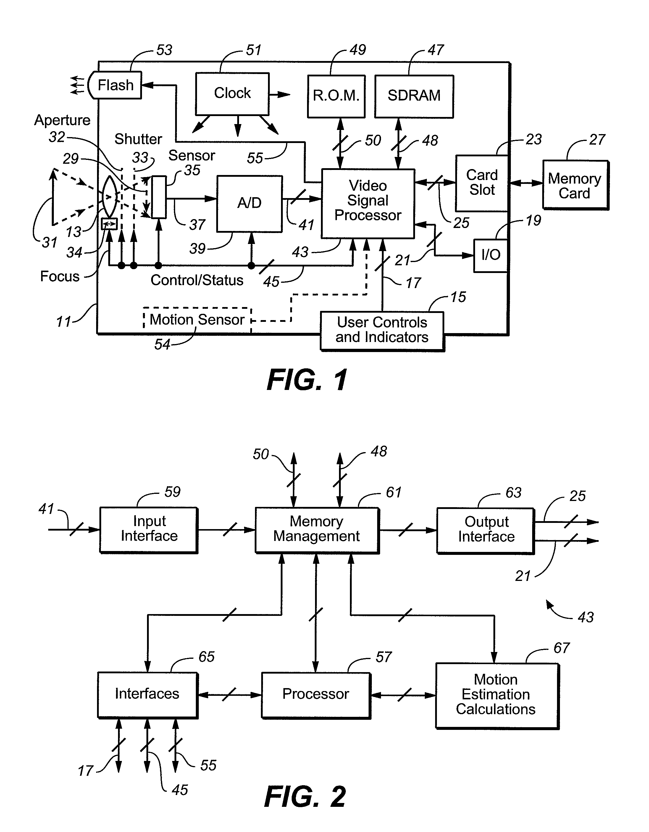
[0029]Video data acquired by a digital camera are typically processed to compensate for imperfections of the camera and to generally improve the quality of the image obtainable from the data. The correction for any defective pixel photodetector elements of the sensor is one processing function that may be performed. Another is white balance correction wherein the relative magnitudes of different pixels of the primary colors are set to represent white. This processing may also include de-mosaicing the individual pixel data to superimpose data from spatially separate monochromatic pixel detectors of the sensor to render superimposed multi-colored pixels in the image data. This de-mosaicing then makes it desirable to process the data to enhance and smooth edges of the image. Compensation of the image data for noise and variations of the camera optical system across the image and for variations among the sensor photodetectors may also be performed. Other processing typically includes on...


PUM


Abstract

Motion of an image of a scene being captured by a digital image acquisition device is detected and used to control parameters of illumination of the scene by a flash lamp that is typically built into the device. Parameters that may be controlled include the intensity, duration and timing of light emitted by the flash lamp. Such control of the flash illumination is preferably performed in conjunction with adjusting one or more exposure parameters used to capture an image. Such exposure parameters include duration, aperture and sensor gain. Motion blur caused by movement of the camera or by movement of an object within the scene being photographed is reduced by selecting appropriate exposure parameters and flash light characteristics.

Description

BACKGROUND AND SUMMARY[0001]This application relates to automatic exposure control of digital cameras and other electronic digital image acquisition devices, and particularly to the control of scene illumination by flash light during the capture of image data of the scene.[0002]Electronic cameras image scenes onto a two-dimensional sensor such as a charge-coupled-device (CCD), a complementary metal-on-silicon (CMOS) device or other type of light sensor. These devices include a large number of photo-detectors (typically two, three, four or more million) arranged across a small two dimensional surface that individually generate a signal proportional to the intensity of light or other optical radiation (including infrared and ultra-violet regions of the spectrum adjacent the visible light wavelengths) striking the element. These elements, forming pixels of an image, are typically scanned in a raster pattern to generate a serial stream of data representative of the intensity of radiatio...

Claims


Application Information

Patent Timeline
Patent Type & Authority Patents(United States)
IPC IPC(8): G03B15/03
CPCH04N5/2354H04N23/74
Inventor POZNIANSKY, ELIPERTSEL, SHIMON
Owner QUALCOMM INC
Why Eureka
Try Eureka