Microscope system and method

a microscopy and system technology, applied in the field of optical techniques, can solve the problems of significant limitation of the utility of fast time-resolved imaging, limited image frame rate, and time-consuming process of imaging, and achieve the effect of facilitating multi-photon microscopy imaging of a sampl

Active Publication Date: 2010-04-13
YEDA RES & DEV CO LTD
View PDF9 Cites 12 Cited by
  • Summary
  • Abstract
  • Description
  • Claims
  • Application Information

AI Technical Summary

Benefits of technology

[0013]The main idea of the present invention is aimed at eliminating or at least significantly reducing mechanical scanning (i.e. relative displacement between a sample and an illuminating light beam) across the sample (i.e. in the focal plane of the microscope). The present invention provides for illuminating a region on the sample of dimensions many orders of magnitude larger than a diffraction-limited spot of the imaging lens arrangement used in the microscope. This is achieved by manipulating an input light pulse to apply spatiotemporal pulse shaping, and thus obtain full-frame depth resolved imaging without scanning.
[0035]According to another broad aspect of the invention, there is provided a method for imaging of a sample by a multi-photon microscope, the method comprising: directing a single short input pulse of a predetermined initial duration onto a scattering surface with a certain non-zero angle of incidence of the input pulse onto said surface, with said surface being accommodated in a front focal plane of an imaging lens arrangement and extending perpendicular to an optical axis of the imaging lens arrangement, thereby affecting a duration of the pulse at any point downstream of said surface, with respect to the pulse propagation towards the sample, and allowing restoration of the initial pulse duration in an imaging plane, to thereby provide traveling of an illumination spot along the imaging plane, thereby illuminating a region significantly larger than a diffraction-limited spot of the imaging lens arrangement.

Problems solved by technology

The imaging is thus a time consuming process, which is typically limited to a few tens of milliseconds per section in current commercial systems, a limit set by the speed of mechanical scanning devices.
This is an inherent limitation of the confocal method, which significantly limits its utility for fast time-resolved imaging.
However, acquisition of an image still requires scanning of either the sample or the laser beam, resulting in a similar restriction of the image frame rate.
Overall, however, frame rates have not been reduced significantly beyond video-rate imaging.

Method used


Image

  • Microscope system and method
  • Microscope system and method
  • Microscope system and method

Examples


Embodiment Construction

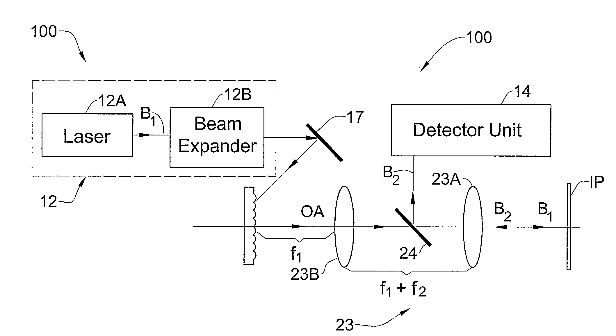
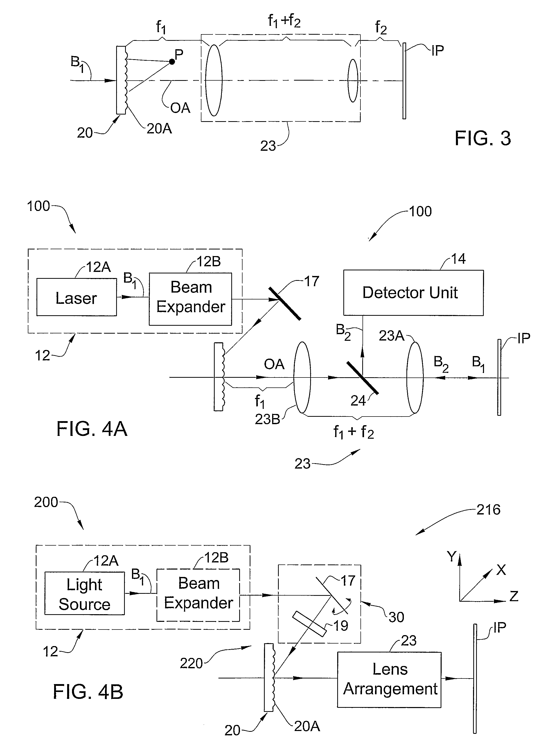
[0047]The present invention provides for depth-resolved imaging, e.g. multiphoton microscopy (e.g., TPEF microscope), or material processing (e.g. patterning), performed without a need for scanning the radiation beam along a sample (i.e. without a need for a relative displacement between an exciting light beam and a sample along a focal plane). In other words, the present invention provides for imaging / processing a sample with a scanningless optical system (e.g. microscope). To this end, the technique of the present invention utilizes temporal focusing of a single input light pulse (rather than spatial focusing), and possibly also utilizes a spatial focusing along one spatial axis.

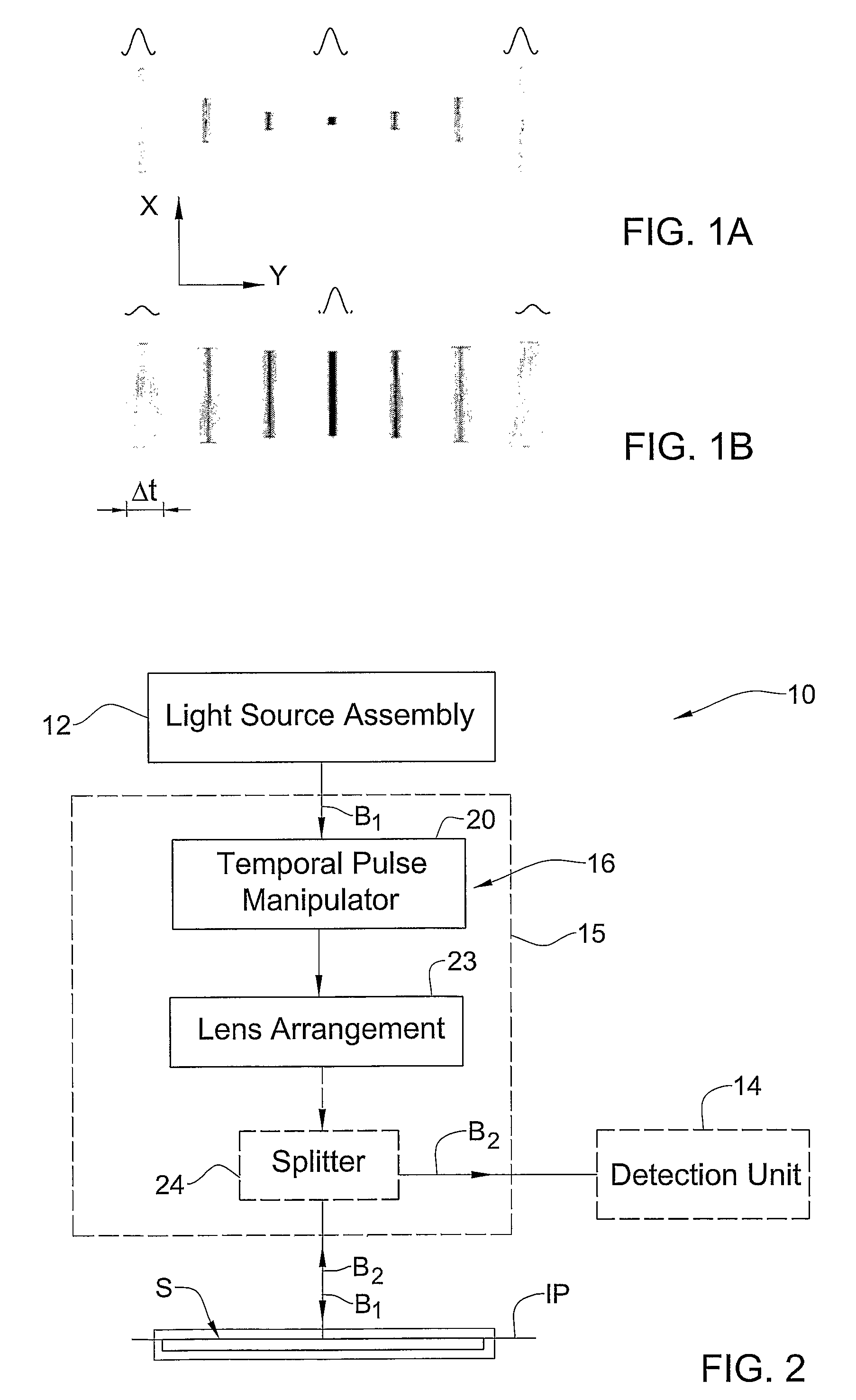
[0048]Referring to FIGS. 1A and 1B there are schematically illustrated the principles of such a scanningless depth resolved microscopy as compared to the standard multiphoton microscopy scheme. Here, the X-axis is the lateral axis extending along the sample (i.e. axis perpendicular to the optical axis of a...


PUM


Abstract

An optical system and method are presented for use in a multi-photon microscope. The system comprises an imaging lens arrangement, and a pulse manipulator arrangement. The pulse manipulator arrangement comprises a temporal pulse manipulator unit which is accommodated in an optical path of an input pulse of an initial profile, and is configured to affect trajectories of light components of the input pulse impinging thereon so as to direct the light components towards an optical axis of the lens arrangement along different optical paths, said temporal light manipulator unit being accommodated in a front focal plane of the imaging lens arrangement, thereby enabling to restore the input pulse profile at an imaging plane.

Description

FIELD OF THE INVENTION[0001]This invention is generally in the field of optical techniques, and relates to a multi-photon method and system for use in microscopy, or in material processing techniques.BACKGROUND OF THE INVENTION[0002]Laser-scanning microscopy, confocal or multiphoton based microscopy, provides for performing optical sectioning.[0003]The confocal microscope, disclosed in U.S. Pat. No. 3,013,467, utilizes optical sectioning of microscopic samples, i.e. the rejection of out-of-focus scattering, by using a confocal pinhole in front of the detection system.[0004]The field of confocal microscopy relies on the idea of point-by-point illumination of a sample and using mechanical scanning (i.e. displacing the light beam and / or the sample) in order to collect an image. The imaging is thus a time consuming process, which is typically limited to a few tens of milliseconds per section in current commercial systems, a limit set by the speed of mechanical scanning devices. This is ...

Claims


Application Information

Patent Timeline
Patent Type & Authority Patents(United States)
IPC IPC(8): G06F19/00
CPCG02B21/06
Inventor SILBERBERG, YARONORON, DAN
Owner YEDA RES & DEV CO LTD
Why Eureka
Try Eureka