Position and orientation measurement method and apparatus

a technology measurement method, applied in the field of positioning and orientation measurement method and apparatus, can solve the problems of reducing detection accuracy, reducing detection accuracy, and unable to calculate the reliability of the calculation, so as to eliminate or reduce the influence of indices, and improve accuracy and stability

Inactive Publication Date: 2010-04-13
CANON KK
View PDF42 Cites 84 Cited by
  • Summary
  • Abstract
  • Description
  • Claims
  • Application Information

AI Technical Summary

Benefits of technology

[0011]The present invention has been made in consideration of the aforementioned problems. That is, the present invention has as its object to measure the position and orientation of an image sensing device with high precision and stability by eliminating or reducing the influences of indices with low detection precision by changing the weights according to evaluation amounts unique to indices having a two-dimensional (2D) shape (circular markers, polygonal markers, or the like).

Problems solved by technology

A problem about registration in the MR eventuates in a problem of calculating the relative position and orientation between a target object on which virtual information is to be superimposed, and the image sensing device (to be referred to as the position and orientation of the image sensing device hereinafter).
For this reason, correct position and orientation measurement often fails due to the large influence of indices as detection errors or those with low detection precision.
However, the attempt that calculates the reliabilities based only on the statistical amounts of the re-projection errors, and weights the indices to eliminate detection errors or to reduce the influences of indices with low detection precision (the precision of image coordinates to be detected) is not always effective.
However, when the number of erroneously detected indices is larger than that of correctly detected indices, the position and orientation measurement may be affected by indices with low detection precision.
Since even indices sensed in a single image may often include those with low detection precision depending on the allocations of markers and the conditions upon image sensing, such indices lead to the drop of the position and orientation measurement precision.

Method used


Image

  • Position and orientation measurement method and apparatus
  • Position and orientation measurement method and apparatus
  • Position and orientation measurement method and apparatus

Examples


first embodiment

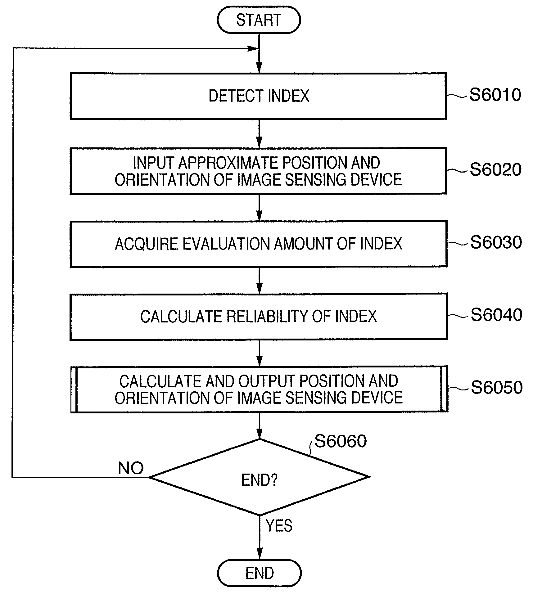
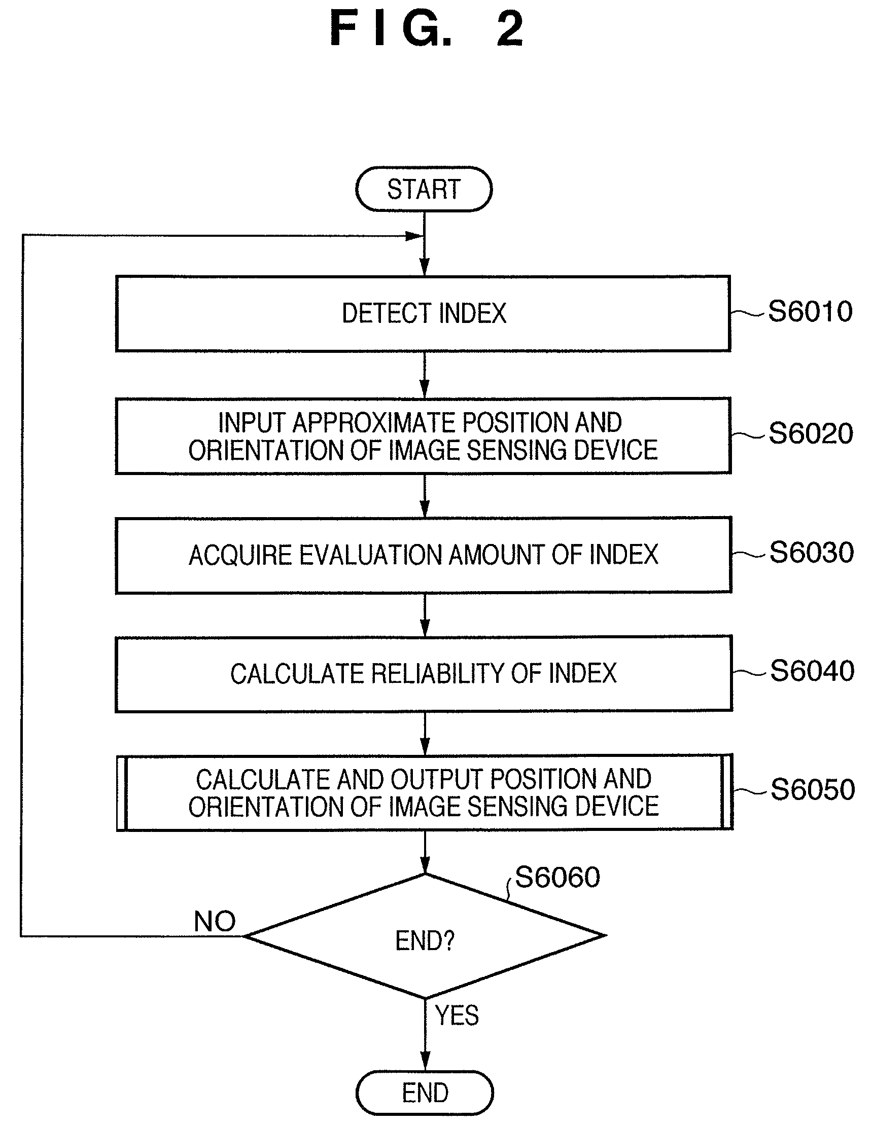
[0030]A position and orientation measurement apparatus for an image sensing device according to this embodiment weights by changing reliabilities according to evaluation amounts of detected indices having a two-dimensional (2D) shape, so as to eliminate indices with low precision or to reduce their influences, thereby improving the precision of the position and orientation measurement result of the image sensing device. The method of measuring the position and orientation of the image sensing device based on weighting in accordance with the evaluation amounts of indices according to this embodiment will be described hereinafter.

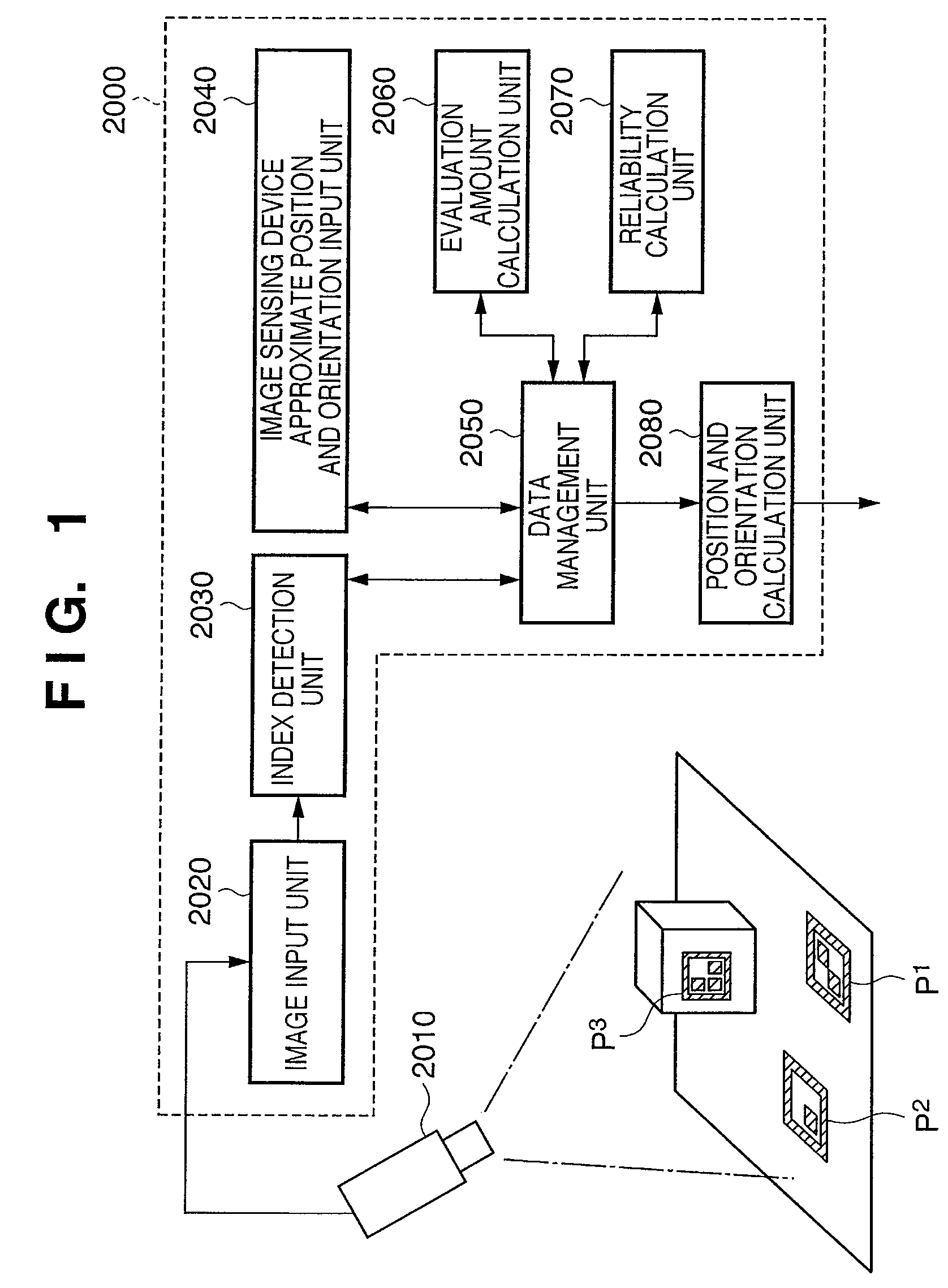
[0031]FIG. 1 shows a schematic arrangement of a position and orientation measurement apparatus 2000 for an image sensing device according to this embodiment. The position and orientation measurement apparatus 2000 comprises an image input unit 2020, index detection unit 2030, image sensing device approximate position and orientation input unit 2040, data mana...

second embodiment

[0088]In the first embodiment, each reliability ωPkn is determined based on the evaluation amount which is obtained based on the relative orientation between the image sensing device and index. However, if the reliability is calculated based on an evaluation amount using the characteristics of a geometric shape of an index having a 2D shape, the type of information used as the evaluation amount is not limited to such specific value. That is, the reliability calculation method may be implemented by another method or a method combined with the other method. For example, 2D geometric information (e.g., an area, aspect ratio, or the like) associated with each index may be acquired from an image, and a reliability may be calculated using that information as an evaluation amount.

[0089]For example, the reliability ωPkn may be calculated using, as an evaluation amount VSPkn, an area SPkn of the detected index on the image. In this case, the image sensing device approximate position and orie...

third embodiment

[0142]The description of the above embodiments is given under the assumption that the respective units which form the position and orientation measurement apparatus 2000 shown in FIG. 1 are implemented by hardware. However, some or all of the units shown in FIG. 1 may be implemented by software, and the remaining units may be implemented by hardware. In this case, this hardware is implemented as a function expansion card which can be inserted into a personal computer, and that function expansion card is inserted into the personal computer. The software is stored on a memory of the personal computer. With this arrangement, a CPU of the personal computer executes the software, and also makes the operation control of the function expansion card, thus implementing the processing described in the first embodiment and various modifications.

[0143]FIG. 6 is a block diagram showing the hardware arrangement of a computer which can be applied to the position and orientation measurement apparat...


PUM


Abstract

An index detection unit (2030) detects indices allocated or set on an object from a sensed image. An evaluation amount calculation unit (2060) calculates evaluation amounts of the indices using two-dimensional geometric features of the indices on the image and / or three-dimensional geometric features that represent relationships between an image sensing device (2010) and the indices on a three-dimensional space. A reliability calculation unit (2070) calculates reliabilities of the indices according to the calculated evaluation amounts of the indices. A position and orientation calculation unit (2080) calculates the position and orientation of the object or the image sensing device (2010) using at least the calculated reliabilities of the indices and information associated with the image coordinates of the detected indices.

Description

BACKGROUND OF THE INVENTION[0001]1. Field of the Invention[0002]The present invention relates to a technique for improving the precision and stability of viewpoint position and orientation measurement.[0003]2. Description of the Related Art[0004]In recent years, studies about mixed reality (MR) that aims at seamless merging of physical and virtual spaces have been extensively made. An MR image is generated by superimposing and rendering virtual space images generated according to the position and orientation of an image sensing device such as a video camera or the like on a physical space image sensed by the image sensing device. An image display apparatus used in an MR system is implemented by, e.g., a video-see-through system. Note that the virtual space images include a virtual object rendered by computer graphics, text information, and the like.[0005]In order to implement the MR, the accuracy of registration between the physical space and virtual space is important, and many app...

Claims


Application Information

Patent Timeline
Patent Type & Authority Patents(United States)
IPC IPC(8): G06F9/00G06F17/40G06F19/00G01B11/00G01B11/26G01C11/04G06F3/033G06F3/041G06T1/00G06T7/60
CPCG01S5/163G06T7/0042G06T2207/30244G06T2207/30204G06T7/73
Inventor ARATANI, SHINICHIUCHIYAMA, SHINJISATOH, KIYOHIDEENDO, TAKAAKI
Owner CANON KK
Why Eureka
Try Eureka