
Aircraft ejection seat with movable headrest

a technology of ejection seat and headrest, which is applied in the direction of aircraft ejection means, pedestrian/occupant safety arrangements, emergency apparatus, etc., can solve the problems of not addressing the aerodynamic lift and flailing problems associated with high-speed ejection, not addressing the tilt-forward or aerodynamic lift issues,

Active Publication Date: 2010-04-20
AMI INDS
View PDF19 Cites 10 Cited by
  • Summary
  • Abstract
  • Description
  • Claims
  • Application Information

AI Technical Summary

Benefits of technology

The present invention provides an ejection seat with a headrest that helps to protect the pilot's head from acceleration and wind blast forces during a ejection. The headrest moves forward to support the pilot's head in a tilted-forward position, which helps to control windblast forces and reduces head impact loads. The headrest includes a pair of struts and a flexible panel to further support the pilot's head. Overall, this invention improves safety for pilots during ejection events.

Problems solved by technology

When a pilot or other aircraft occupant ejects from an aircraft moving at high speed, his or her body is subjected to various acceleration and aerodynamic conditions that if not properly controlled may lead to injury.
After the seat has cleared the aircraft, aerodynamic forces acting on the helmet and ejection seat may interact to cause the crewmember's head to flail in the windblast.
This approach addresses the problem of the crewmember's head tilting forward upon initial acceleration but does not address the aerodynamic lift and flailing problems associated with high-speed ejection.
This approach addresses the problem of the crewmember's head flailing in the windblast but does not address the tilt-forward or aerodynamic lift issues.
This approach addresses the problem of the crewmember's helmet lifting off the crewmember's head and purports to address the issue of head flailing in the wind blast, but does not address the problem of the crewmember's head tilting forward and jerking back as acceleration forces give way to wind blast forces and may impede the crewmember's separation from the seat when the crewmember's parachute deploys.

Method used


Image

  • Aircraft ejection seat with movable headrest
  • Aircraft ejection seat with movable headrest
  • Aircraft ejection seat with movable headrest

Examples


Embodiment Construction

[0014]The drawing figures are intended to illustrate to the general manner of construction and are not necessarily to scale. In the detailed description and in the drawing figures, specific illustrative examples are shown and herein described in detail. It should be understood, however, that the drawing figures and detailed description are not intended to limit the invention to the particular form disclosed, but are merely illustrative and intended to teach one of ordinary skill how to make and / or use the invention claimed herein and for setting forth the best mode for carrying out the invention.

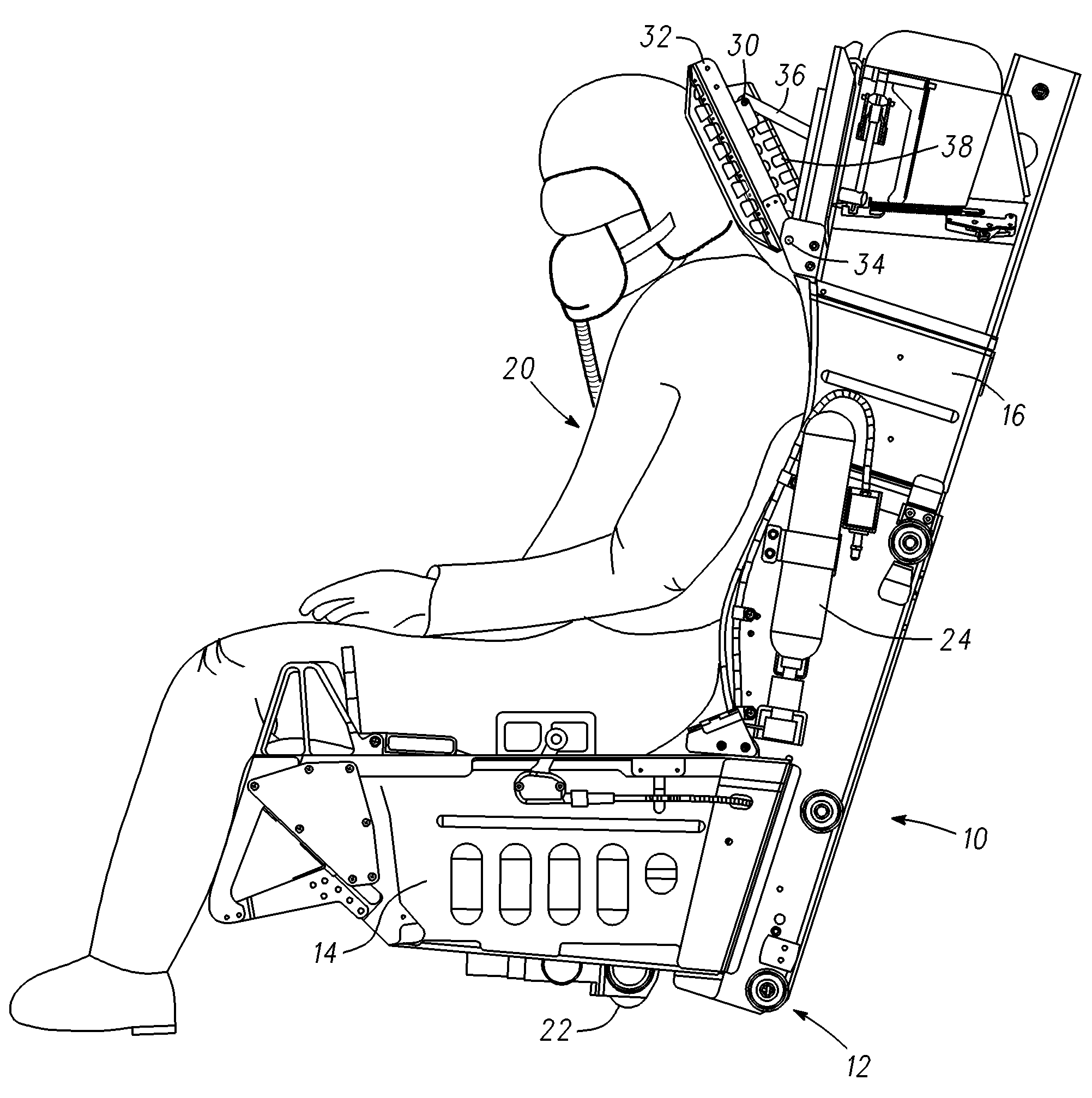
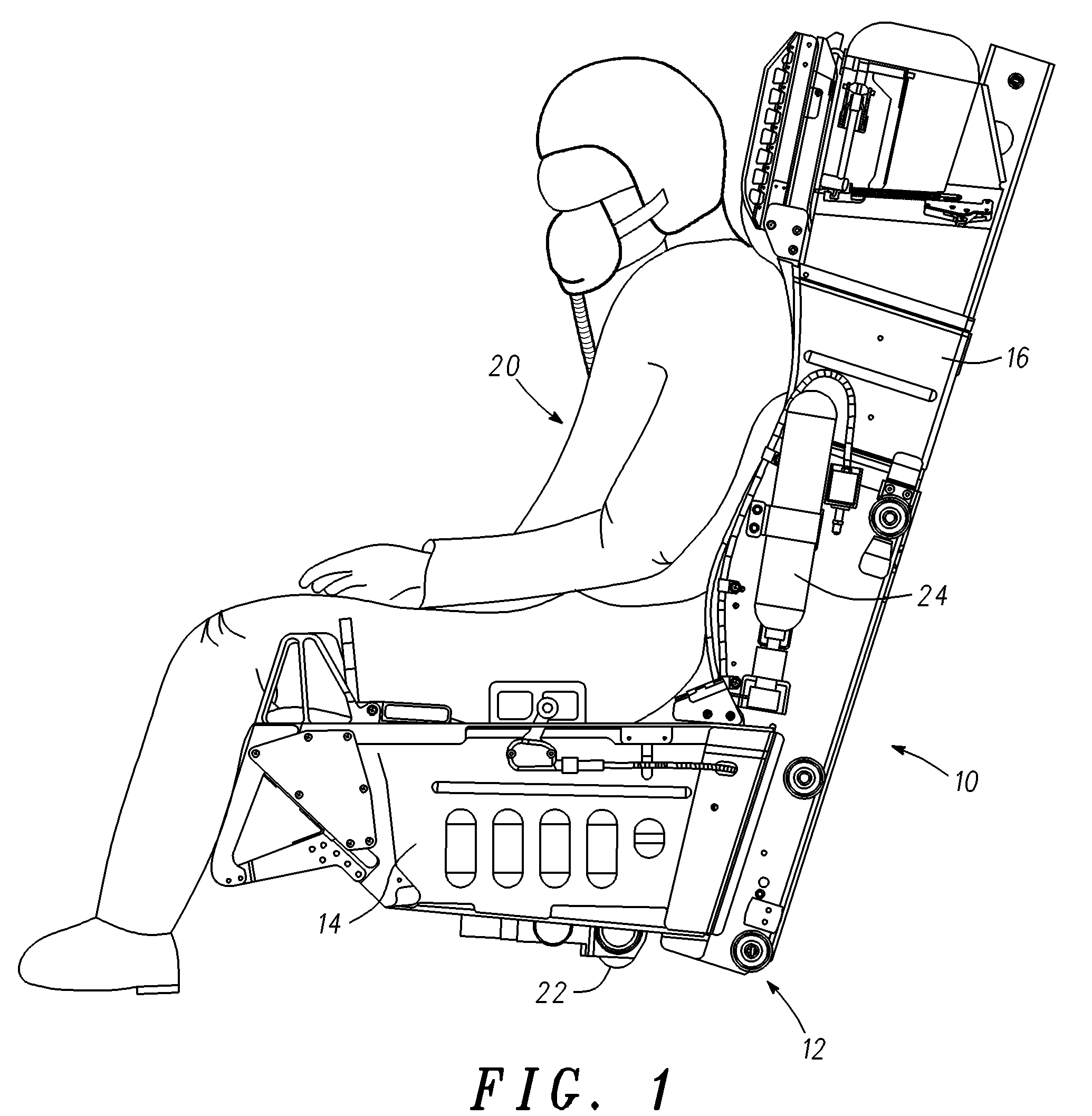
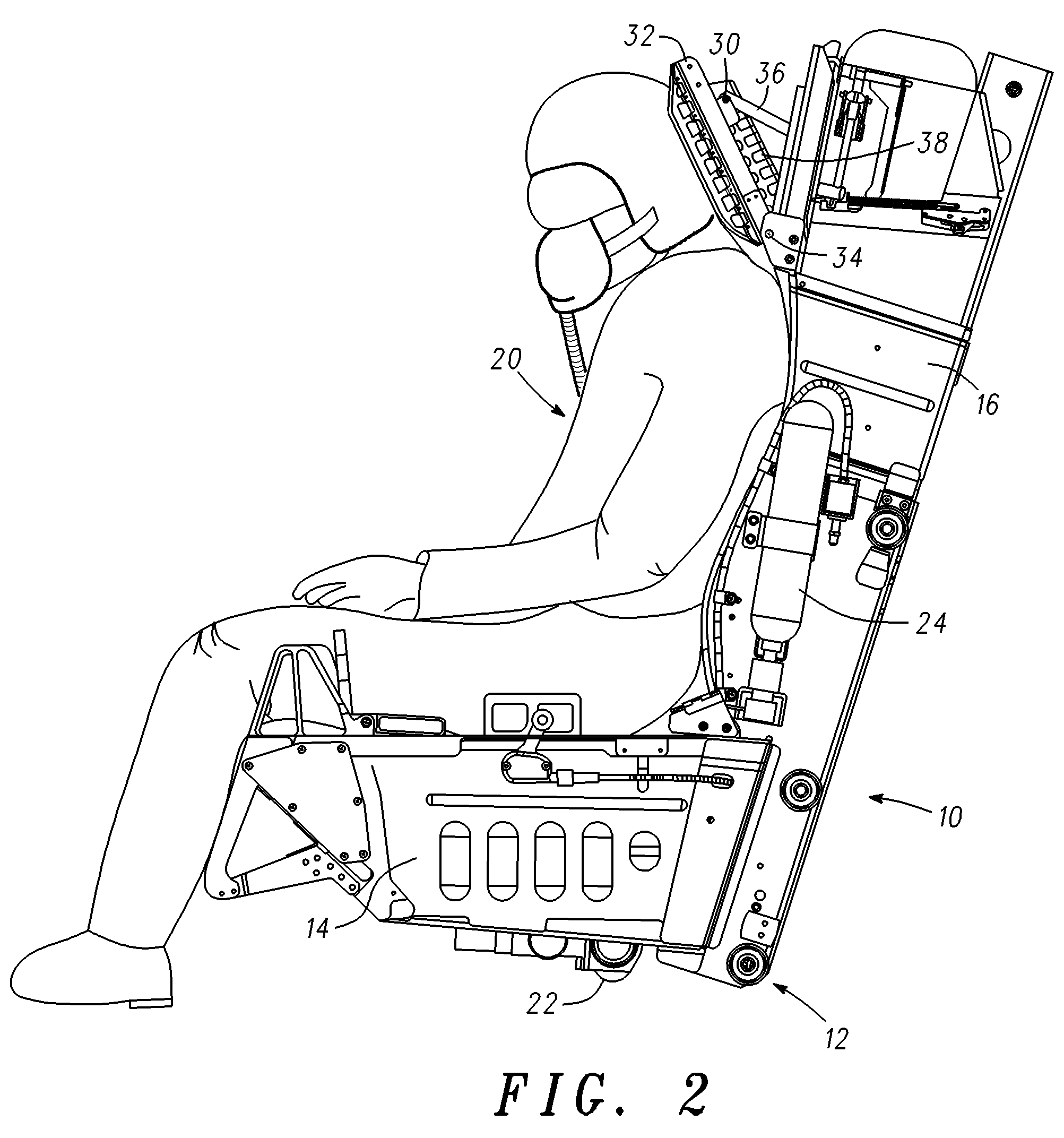
[0015]With references to FIGS. 1-3, an ejection seat 10 incorporating features of the present invention comprises a seat frame 12 consisting of a seat portion 14 and a back portion 16 adapted to support an aircraft occupant such as pilot 20. Ejection seat 10 is equipped with a propulsion subsystem typically consisting of a catapult and a rocket motor 22 for propelling the seat frame free of ...


PUM


Abstract

An ejection seat includes a headrest that, upon initiation of the ejection seat, moves forward to support the pilot's head in a tilted-forward position. By holding the crewmember's head in a tilted-forward position, windblast forces are controlled to prevent the helmet from pulling upward and backward on the crewmember's head. The headrest may include a pair of struts that extend forward around the sides of the crewmember's helmet to support the crewmember's head against flailing from the windblast. A flexible panel extending between the struts and the headrest panel may also be included to further support the crewmember's head against windblast flailing.

Description

CROSS-REFERENCE TO RELATED APPLICATIONS[0001]The application claims priority of provisional application Nos. 60 / 893,039 filed Mar. 5, 2007 and 60 / 894,636 filed Mar. 13, 2007.BACKGROUND OF THE INVENTION[0002]This invention relates to aircraft interior equipment, and more particularly, to aircraft ejection seats.[0003]When a pilot or other aircraft occupant ejects from an aircraft moving at high speed, his or her body is subjected to various acceleration and aerodynamic conditions that if not properly controlled may lead to injury. One area of particular concern is the crewmember's head and neck. During the initial acceleration of the ejection seat, acceleration forces acting on the crewmember's head and helmet tend to pitch the crewmember's head forward and down, this effect is especially pronounced if the helmet is equipped with night vision and / or heads-up-display equipment mounted forward of the crewmember's face. Next, aerodynamic flow over the top of the helmet causes a large pr...

Claims


Application Information

Patent Timeline
Patent Type & Authority Patents(United States)
IPC IPC(8): B64D25/06
CPCB64D25/10
Inventor MASTROLIA, BRAD
Owner AMI INDS
Learn More