Repairable endoscope

a technology of endoscopes and endoscopes, which is applied in the field of endoscopes, can solve the problems of damage to the endoscope, distortion or degradation of the image quality, and other stresses on the endoscope during normal use, and achieves the effects of convenient repair, easy manufacturing, and easy repair

Active Publication Date: 2010-04-20
INTUITIVE SURGICAL OPERATIONS INC
View PDF33 Cites 18 Cited by
  • Summary
  • Abstract
  • Description
  • Claims
  • Application Information

AI Technical Summary

Benefits of technology

[0014]Therefore it is an object of this invention to provide an endoscope that is easy to repair.
[0016]Still another object of this invention is to provide an endoscope that is easy to manufacture, facilitates necessary adjustments during manufacture and is readily disassembled and reassembled during repair.
[0018]In accordance with another aspect of this invention, an autoclavable endoscope has distal and proximal ends and comprises outer housing and optics subassemblies. The outer housing subassembly has a central lumen therethrough. The optics subassembly includes a tubular sheath extending through the central lumen and having sealed windows at each of the distal and proximal ends. A plurality of optical elements in the tubular sheath forming an image of an object and presenting the image for viewing. A material intermediate the outer housing and the tubular sheath prevents displacement therebetween during normal use. The material has a tear strength that permits the separation of the optics subassembly from the outer housing subassembly.

Problems solved by technology

Experience has shown that repeated autoclaving of rigid endoscopes can damage seals whereupon steam can enter the endoscope with resultant condensation in the optical path distorting or degrading the quality of the image.
Endoscopes are also subject to other stresses during normal use.
Should any of these or a number of other events occur, damage can result to the endoscope.
Many endoscopes are integral assemblies, so they can not be repaired.
Replacing, rather than repairing, a damaged endoscope is very expensive.
Although the Bodor et al. patent suggests the use of interchangeable image transmission units, there is no disclosure of the exact structure and process for achieving that result except by reference to “interlocking” and a “mechanical latch” which are not readily ascertained by the disclosure.
This approach, however, still requires repairs at a qualified repair facility.

Method used


Image

  • Repairable endoscope
  • Repairable endoscope
  • Repairable endoscope

Examples


Embodiment Construction

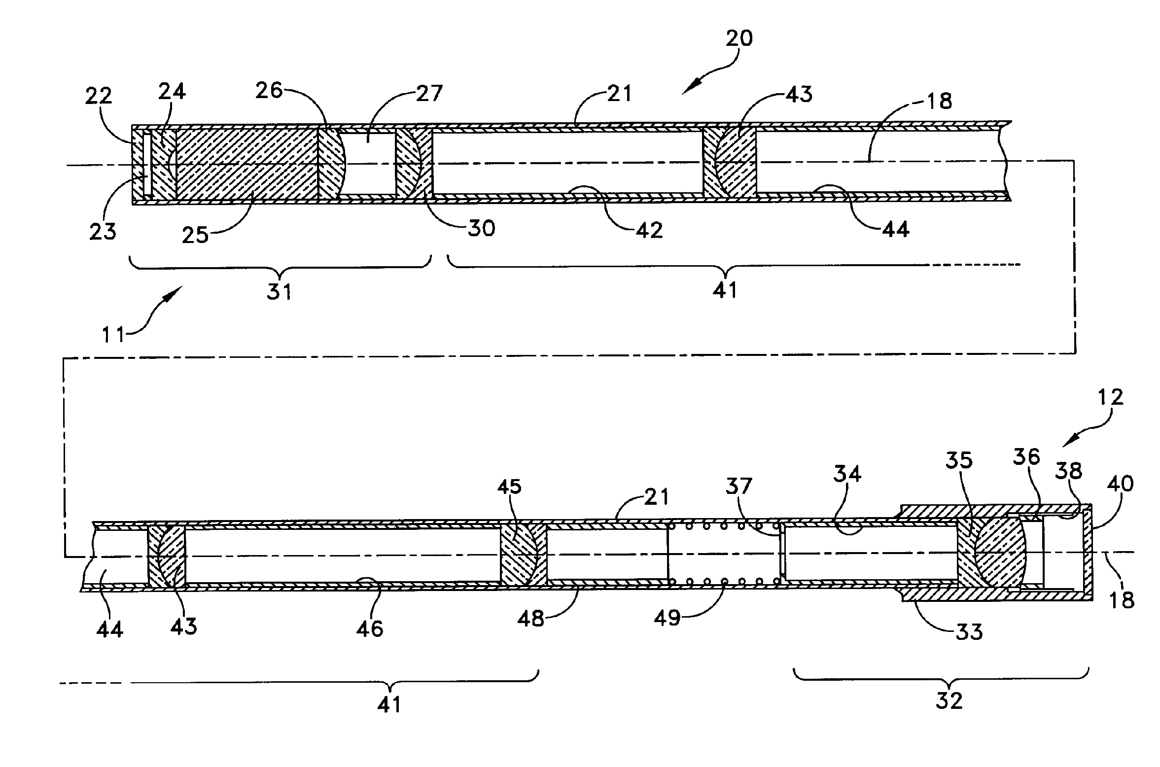
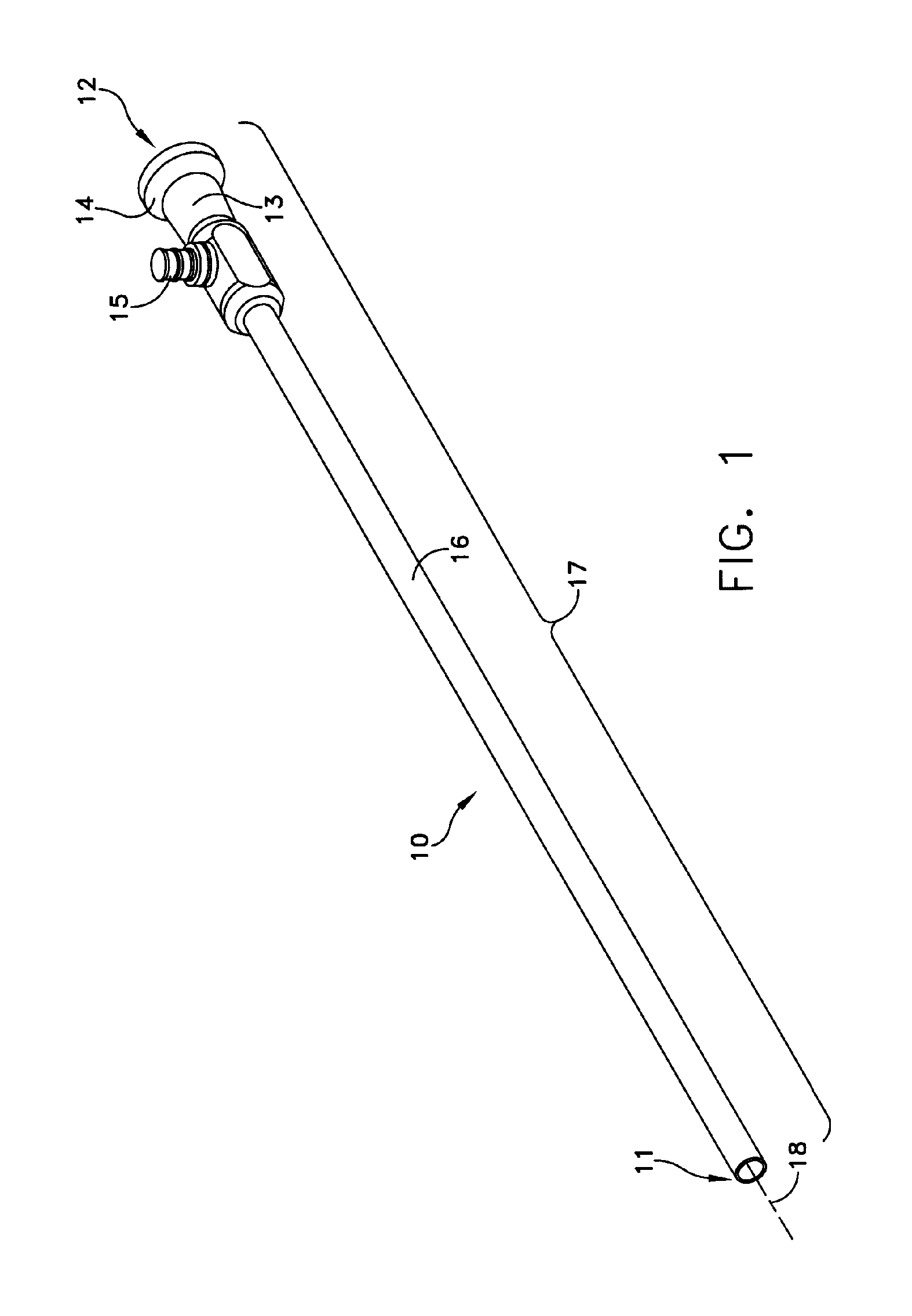
[0029]FIG. 1 depicts an endoscope 10 as it appears to medical personnel for use. It extends between a distal end 11, the end closest to the object to be imaged, and a proximal end 12, the end closest to the person using the device. This view depicts an optical body 13 with an eyecup 14 through which the image is viewed. A fiber post 15 receives an output connection from an illumination source thereby to provide light for transmission through optical fiber to illuminate the object being imaged. An outer sheath of a tube 16 extends from the optical body. All of these elements constitute components of an outer housing subassembly 17 that extends along an optical axis 18.

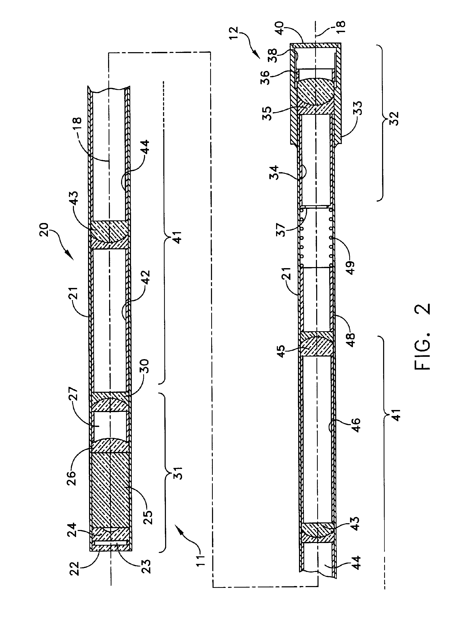
[0030]The endoscope 10 houses an optics subassembly 20 as shown in FIG. 2. Specifically the optics subassembly 20 includes a tubular sheath 21 that extends along the optical axis 18. A distal window 22 that is formed of any material that will withstand autoclaving temperatures, seals the tubular sheath 21 at the distal ...


PUM


Abstract

A rigid endoscope includes an outer housing subassembly that supports an optics subassembly. The outer housing subassembly includes concentric tubes with optical fiber for providing object illumination. The optics subassembly includes a tubular sheath sealed at both ends for carrying lenses and other optical elements. A slow-curing adhesive material fills an annular gap between the optics and outer housing subassemblies. The adhesive material has a tear strength that seals and positions the optics subassembly for normal use and that enables the optics subassembly to be withdrawn from the outer housing subassembly for repair.

Description

CROSS REFERENCE TO RELATED APPLICATION[0001]This application incorporates by reference U.S. patent application Ser. No. 10 / 383,236 to Forkey et al. filed Mar. 6, 2003, now U.S. Pat. No. 6,955,644 granted Oct. 8, 2005 for an Autoclavable Endoscope, assigned to the same assignee as the present application.FIELD OF THE INVENTION[0002]This invention relates to endoscopes adapted for repair and more particularly to autoclavable endoscopes adapted for repair.DESCRIPTION OF RELATED ART[0003]Endoscopes come in two basic forms. In one form the endoscope is flexible. Optical fibers transfer an image from an optical objective to an eyepiece or other viewing device. The fibers produce image pixels of the image from the optical objective. Endoscopes of the second form are called rigid endoscopes. This invention is particularly applicable to rigid endoscopes. A rigid endoscope includes a tubular structure that carries an optical objective at a distal end and a relay lens system that transfers the...

Claims


Application Information

Patent Timeline
Patent Type & Authority Patents(United States)
IPC IPC(8): A61B1/06
CPCA61B1/00096A61B1/00101A61B1/0011A61B1/07A61B1/00071A61B1/0055
Inventor FORKEY, RICHARD E.BARNES, WILLIAM P.ROSS, ROBERT N.FORKEY, JOSEPH N.
Owner INTUITIVE SURGICAL OPERATIONS INC
Why Eureka
Try Eureka