
Access platform for internal mammary dissection

a technology for accessing platforms and internal mammary arteries, which is applied in the field of retractors, can solve the problems of reducing the working space of surgeons, affecting the efficiency of the operation, so as to facilitate the dissection of internal mammary arteries and improve the surgeon's working space. , the effect of increasing the surgeon's working space and visual access to the ima

Inactive Publication Date: 2010-04-20
MAQUET CARDIOVASCULAR LLC
View PDF24 Cites 10 Cited by
  • Summary
  • Abstract
  • Description
  • Claims
  • Application Information

AI Technical Summary

Benefits of technology

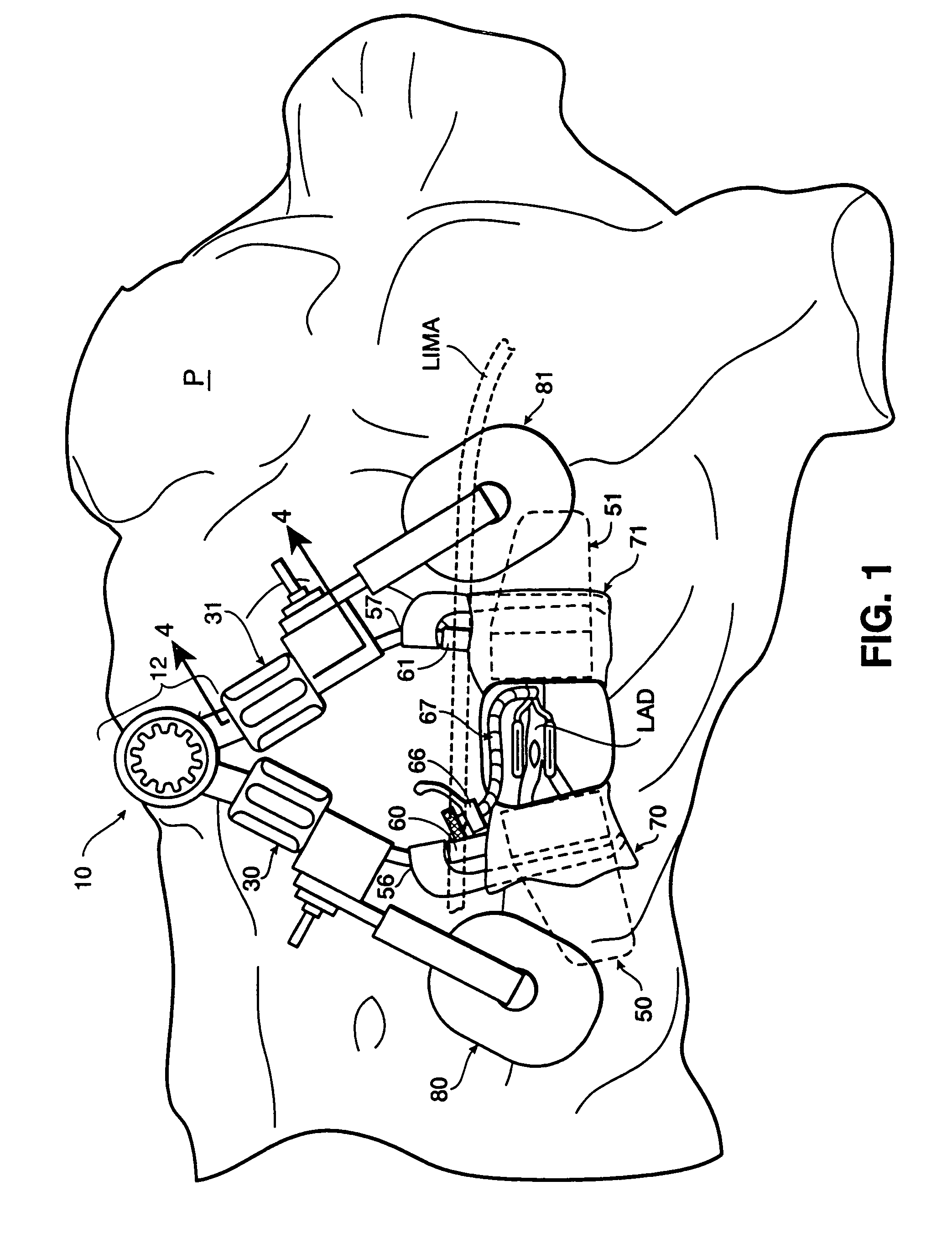
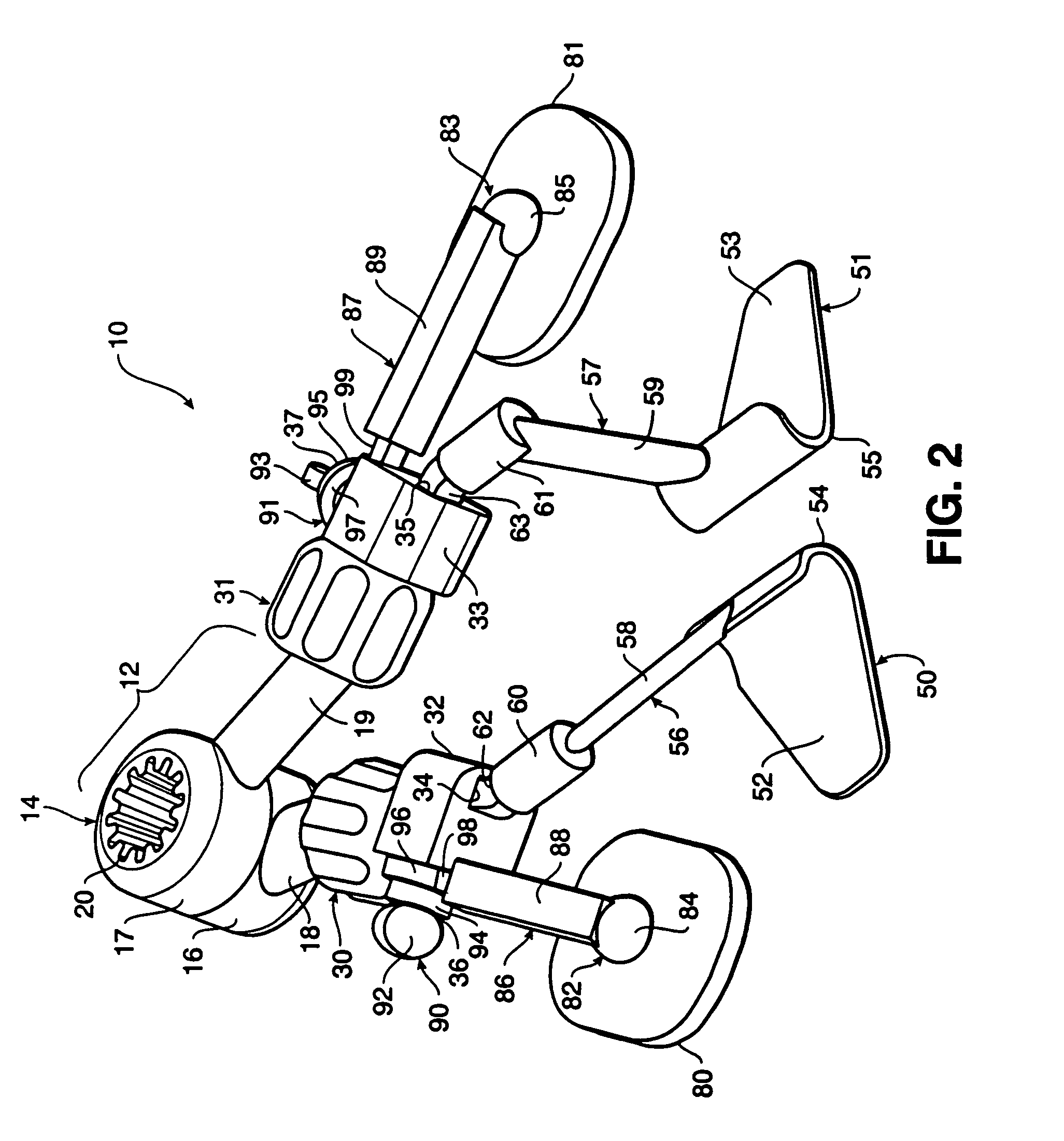
[0018]The access platform of the present invention serves to facilitate the dissection of an internal mammary artery (IMA), including both proximal and distal dissection, and access to the heart during a “beating heart” Coronary Artery Bypass Graft (CABG) procedure by increasing the surgeon's working space and visual access. The access platform of the present invention is preferably capable of laterally spreading the ribs, vertically displacing the opposingly retracted ribs relative to each other and depressing the sternum to cause a “tunnel” effect under the retracted ribs. Moreover, it is preferably self-contained such that the force necessary to spread and vertically displace the ribs is applied by the access platform itself rather than through additional external devices. The access platform preferably comprises first and second blades interconnected to a spreader member that laterally drives the blades apart or together, a sternal pad interconnected to the blades, and a vertical displacement member interconnected to a blade and the spreader member. The vertical displacement member may preferably be bi-directional to cause the interconnected blade to be vertically displaced in either direction and, thus, increases the surgeon's working space and visual access to the IMA.

Problems solved by technology

Diseases of the cardiovascular system affect millions of people each year and are a leading cause of death in the United States and throughout the world.
The cost to society from such diseases is enormous both in terms of lives lost and the cost of treating cardiac disease patients through surgery.
Although the CABG procedure has become relatively common, i.e., heart bypass surgery is performed in one of every thousand persons in the United States, the procedure is lengthy and traumatic and can damage the heart, the central nervous system, and the blood supply.
Despite these advantages, the beating-heart CABG procedure is not widely practiced, in part, because of the difficulty in performing the necessary surgical procedures with conventional instruments while the heart is still beating.
Since the “beating heart” CABG procedure is performed while the heart muscle is continuing to beat or contract, an anastomosis is difficult to perform because the blood continues to flow and the heart continues to move while the surgeon is attempting to sew the graft in place.
Also, the surgeon's working space and visual access are limited because the surgeon may be working through a small incision in the chest or may be viewing the procedure on a video monitor, such that the site of the surgery is viewed via a surgical scope.
However, the surgeon's assistant must then hold the rib in a vertically displaced position for the duration of the IMA dissection, resulting in an undesirable addition of another set of hands around the surgical area.
However, it is not at all uncommon for the patient to be raised off the operating table by the winch.
This is undesirable because if the rib begins to crack or break, the weight of the patient's body will cause the rib to continue to break until the patient reaches the operating table.
However, depression of the sternum or the other retracted rib undesirably adds further sets of hands around the surgical site.
Furthermore, these methods and devices tend to limit where the thoracotomy can be performed.
In addition, if a winch is used to offset the ribs, the lifting action of the winch will tend to rotate the patient to an undesirable and often unstable position for performing the IMA.
However, none of the methods or devices described above provide the ability to perform soft tissue retraction.

Method used


Image

  • Access platform for internal mammary dissection
  • Access platform for internal mammary dissection
  • Access platform for internal mammary dissection

Examples


first embodiment

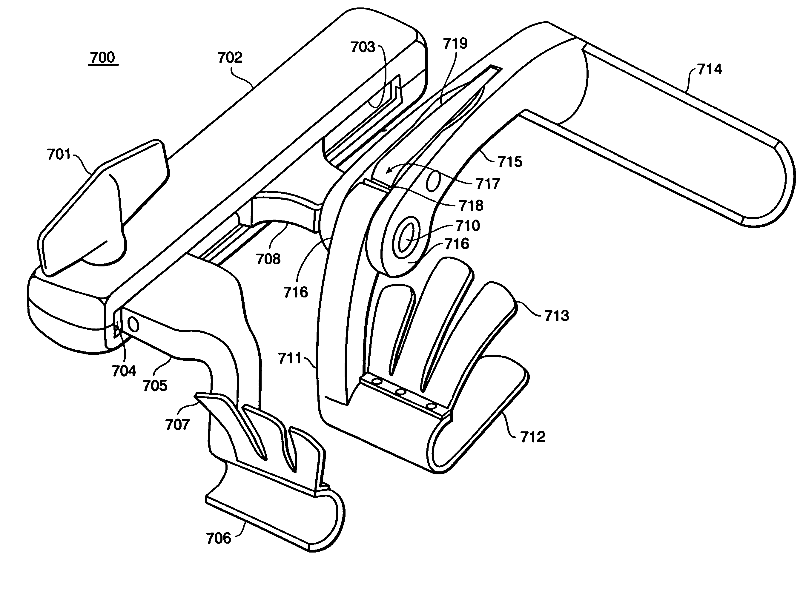
[0146]As in the first embodiment, after the ribs have been vertically displaced, tissue retractors 70, 71 or 100 (shown in FIGS. 5-12) are operated to retract the soft tissue away from the incision area by either rotating the arms 72A and 72B about the pivots 150 and 151 on the blade arms 146 and 147 or bending or displacing the fingers 101A, 101B, and 101C over the patient's chest. By rotating the arms 72A and 72B about the pivots 150 and 151, the elastic sheets 77A and 77B advantageously grab, pull, and press down against the soft tissue to retract it away from the incision and out of the surgeon's working area. By bending or displacing the retractor fingers 101A, 101B and 101C over the patient's chest the fingers 101A, 101B and 101C advantageously press down against the soft tissue to retract it away from the incision and out of the surgeon's working area.

[0147]In a first offset position, the blade 141 raises the retracted ribs and the blade 140 depresses the retracted ribs so th...

eighth embodiment

[0163]Referring to FIGS. 24 and 25, the access platform 310 of the present invention includes telescoping arms 390 and 392 incorporated with the access platform 310 shown in FIG. 18. The telescoping arms 390 and 392 are perpendicularly disposed between and releasably attached to the blades 350 and 352. In addition, the blade arms 338 and 340 include branch extensions 347 and 349 releasably coupled at break lines B1 and B2 to the branches 346 and 348 (FIG. 25).

[0164]In operation, the blades 350 and 352 are inserted in an incision in the chest to capture the ribs. The lever 326 is then rotated to drive pinion 324 along the rack 320 and spread the ribs. Once the ribs are retracted to a desired spacing, the telescoping arms 390 and 392 are connected to the blades 350 and 352 and engaged to hold the blades 350 and 352 apart. The branches 346 and 348 are then decoupled from the branch extensions 347 and 349. The remainder of the access platform 310 can be moved away from the surgical site...

ninth embodiment

[0166]Turning to FIG. 26, the access platform 410 of the present invention is shown. The access platform 410 mounts to the table or rail via slides 438 and 440 that are locked in place by positioners 450 and 452. The slides 438 and 440 rotatably retain pinions 442 and 444 driven by levers 446 and 448 and slidably receive stanchion racks 430 and 432. The stanchion racks 430 and 432 include rack gears 434 and 436 that operably couple with pinions 442 and 444. The levers 446 and 448 are rotated to drive the pinions 442 and 444 along rack gears 434 and 436 to adjust the height of the stanchion racks 430 and 432 relative to the table or patient, or to vertically offset blades 470 and 472 relative to one another.

[0167]A pinion housing 422 is slidably attached to the stanchion rack 432 towards its upper end. A rack 420 is attached at one end to stanchion rack 430 and is slidably received in the pinion housing 422. A pinion 424 driven by a lever 426 is rotatably retained in the pinion housi...


PUM


Abstract

An access platform having a first and a second blade interconnected to a spreader member that laterally drives the blades apart or together and a sternal pad interconnected to a blade. The superior blade is pivotally coupled to the spreader member such that it naturally rises as the blades are separated. Alternatively, a vertical displacement member is operably interconnected to a blade and the spreader member and is used to vertically displace the interconnected superior blade and, thus, increase a surgeon's working space and visual access for the dissection of an internal mammary artery. A tissue retractor is interconnected to the blades to draw the soft tissue around an incision away from the surgeon's working area.

Description

[0001]This application is a continuation of application Ser. No. 08 / 903,516, filed on Jul. 30, 1997, now issued as U.S. Pat. No. 5,944,736, which in turn is a continuation of Ser. No. 08 / 787,748, filed on Jan. 27, 1997, now abandoned, which in turn is a continuation-in-part of application Ser. No. 08 / 619,903, filed on Mar. 20, 1996, now issued as U.S. Pat. No. 5,976,171, which in turn is a continuation-in-part of application Ser. No. 08 / 604,161, filed on Feb. 20, 1996, now issued as U.S. Pat. No. 5,730,757, the disclosures of which are incorporated herein by reference as if set forth in full.DESCRIPTION[0002]1. Field of the Invention[0003]This invention relates to retractors, and more particularly to an access platform that facilitates access to the interior of the chest cavity during surgical procedures.[0004]2. Background of the Invention[0005]Diseases of the cardiovascular system affect millions of people each year and are a leading cause of death in the United States and through...

Claims


Application Information

Patent Timeline
Patent Type & Authority Patents(United States)
IPC IPC(8): A61B17/02A61M29/00A61B17/34A61B19/00
CPCA61B17/0206A61B19/26A61B17/3423A61B17/025A61B2017/349A61B17/3476A61B90/50A61B2017/3427
Inventor TAYLOR, CHARLES S.ALDRICH, WILLIAM N.BENETTI, FEDERICO J.GINN, RICHARD S.MOREJOHN, DWIGHT P.REGAN, BRENTREIS, EUGENE E.SEPETKA, IVANWITT, WILLIAM F.
Owner MAQUET CARDIOVASCULAR LLC
Learn More