Battery and battery assembly

a battery and battery technology, applied in the field of batteries, can solve the problems of poor mass productivity and high cost, and achieve the effects of reducing the number of assembling steps and components, improving mass productivity, and reducing costs

Inactive Publication Date: 2010-04-20
PANASONIC CORP
View PDF16 Cites 4 Cited by
  • Summary
  • Abstract
  • Description
  • Claims
  • Application Information

AI Technical Summary

Benefits of technology

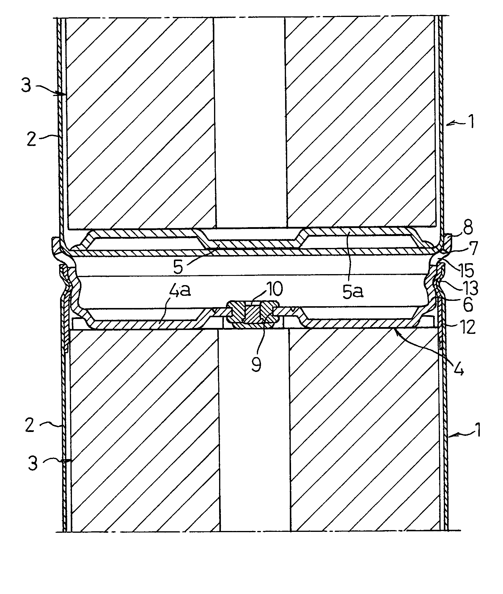
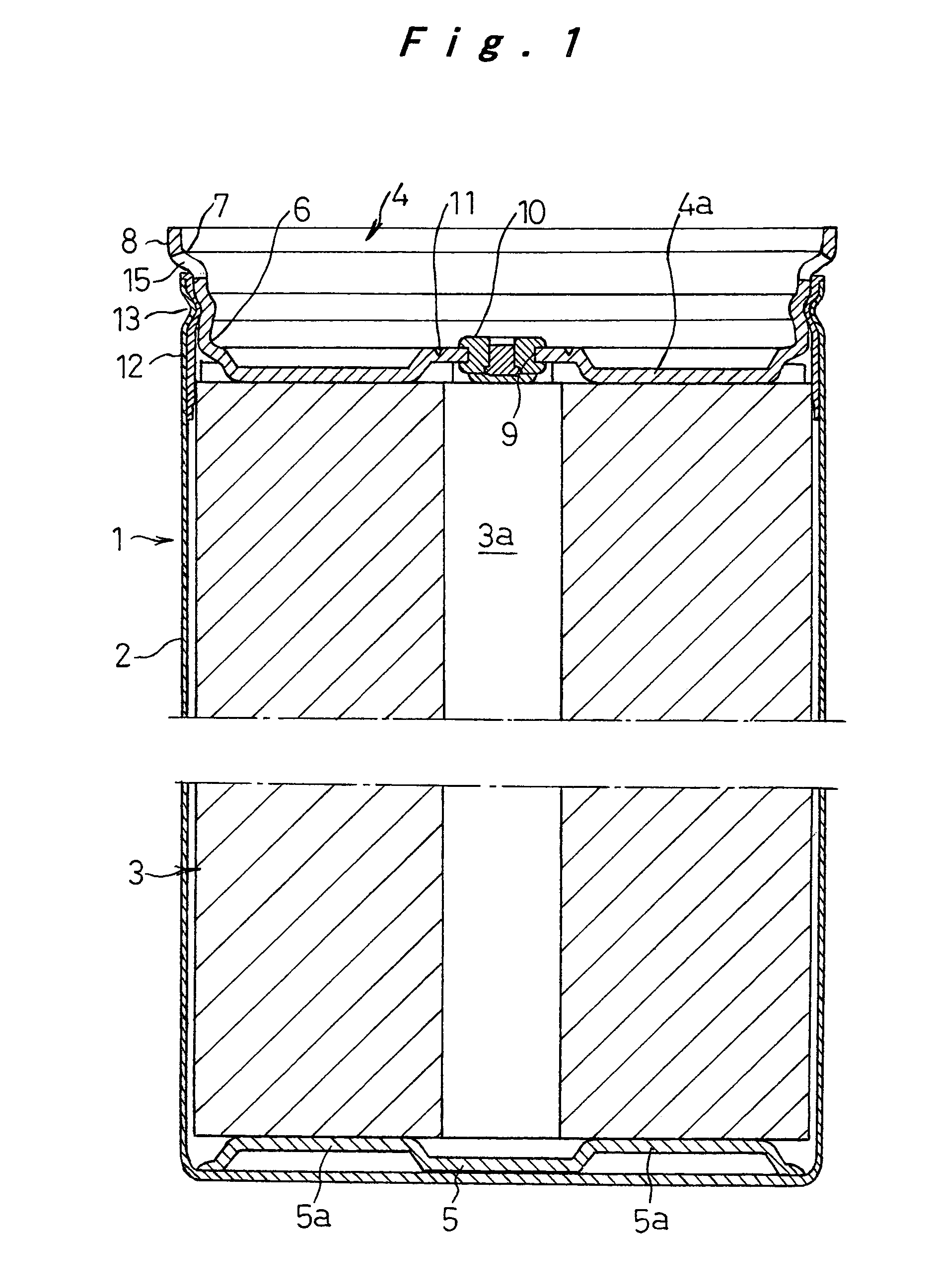
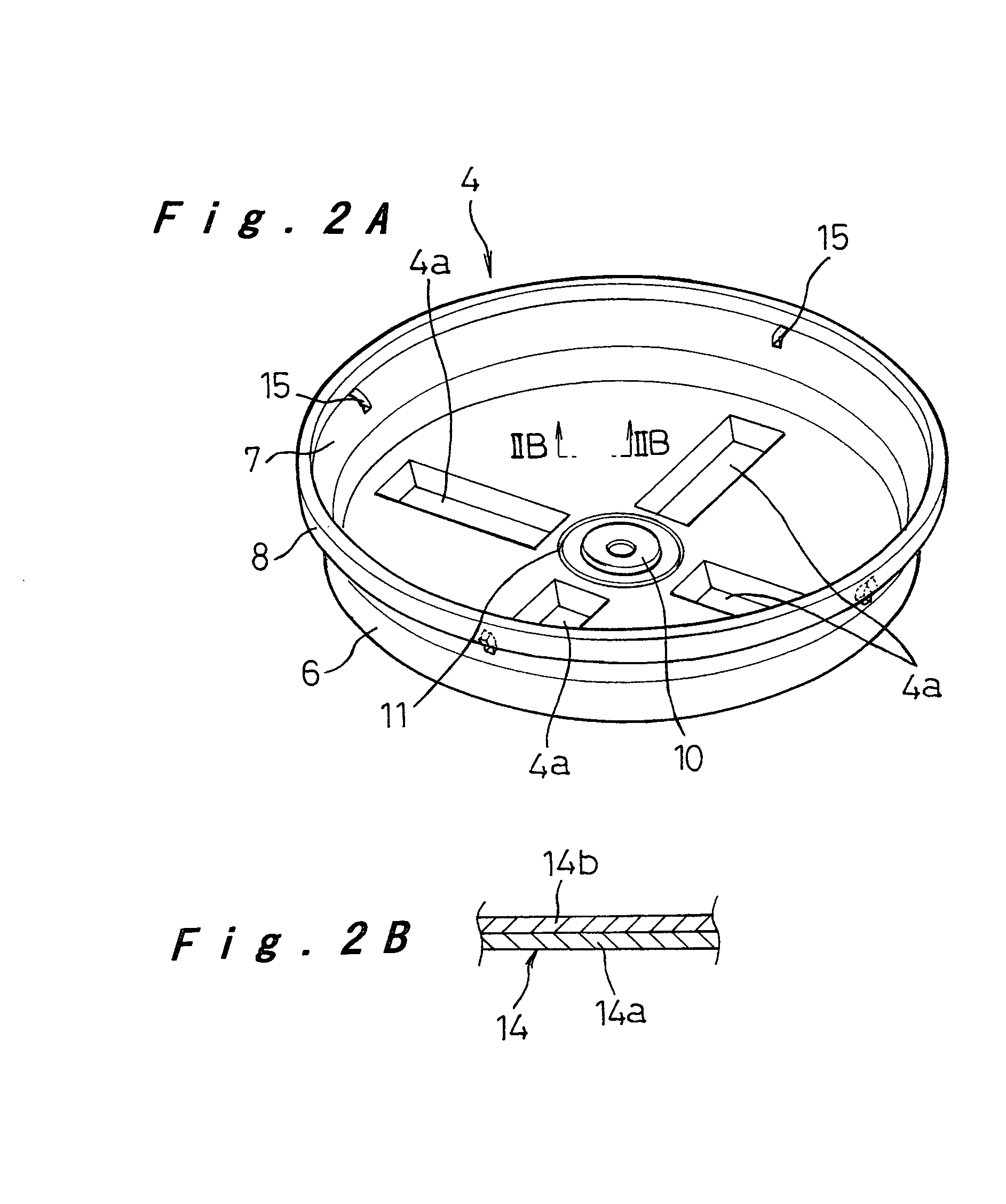
[0009]A battery according to a first aspect of the present invention includes: an electrode assembly that consists of a positive electrode plate and a negative electrode plate, and a separator wound or laminated together, core materials of the negative and positive electrode plates being bared respectively at either end; a bottomed cylindrical outer case having a bottom being connected to either end face of the electrode assembly to serve as a battery terminal; electrolyte impregnated in the electrode assembly; and a lid connected to the other end face of the electrode assembly and fixedly attached to the outer case with sealing means and insulation means interposed therebetween. The lid includes a connecting part in one piece therewith that engages with and connects a bottom part of the outer case of another battery to be connected, a hole for pouring the electrolyte into the battery, and safety means for releasing gas in response to an increasing of internal pressure. Battery outer cases are connected with each other using the connecting part that is in one piece with the lid, and separate connecting members that were conventionally used for connecting batteries are not necessary. The numbers of assembling steps and components are thereby reduced, the cost is lowered, and mass productivity is improved. Moreover, the battery has higher power output because of the reduced internal resistance per cell.
[0010]A battery according to a second aspect of the present invention includes: an electrode assembly that consists of a positive electrode plate and a negative electrode plate, and a separator wound or laminated together, core materials of the positive and negative electrode plates being bared respectively at either end; a bottomed cylindrical outer case having a bottom being connected to either end face of the electrode assembly to serve as a battery terminal; electrolyte impregnated in the electrode assembly; and a lid connected to the other end face of the electrode assembly and fixedly attached to the outer case with sealing means and insulation means interposed therebetween. The lid includes a hole for pouring the electrolyte into the battery and safety means for releasing gas in response to an increasing of internal pressure, and is welded to the bared portion of the core material of one of the electrode plates of the electrode assembly so as to double as a current collector plate. Since the current collector plate and a tab for connecting the plate with the lid are omitted, the numbers of components and weld points are reduced and a cost reduction is achieved. Furthermore, the battery power output is improved because of the reduced current path length and resistance.
[0011]The lid may be welded to the bared portion of the core material of one of the electrode plates of the electrode assembly so as to double as a current collector plate in the above battery according to the first aspect of the invention, whereby a cost reduction is achieved and battery power output is further improved.

Problems solved by technology

The assembling process thus includes assembly of the battery pack, mounting of the connecting members 35, and connection of other batteries, i.e., it takes numbers of components and assembling steps and the costs high, resulting in a poor mass productivity.

Method used


Image

  • Battery and battery assembly
  • Battery and battery assembly
  • Battery and battery assembly

Examples


Embodiment Construction

[0025]One embodiment of a battery and a battery pack applied as a lithium ion battery according to the present invention will be hereinafter described with reference to FIG. 1 to FIG. 4.

[0026]In FIG. 1, reference numeral 1 denotes a battery cell consisting of an electrode assembly 3 accommodated in an outer case 2 with electrolyte and sealed with a lid 4. The outer case 2 is a bottomed cylindrical, deep drawn part of nickel or stainless steel plate that is resistant to the electrolyte.

[0027]The electrode assembly 3 is formed by winding together a positive electrode plate and a negative electrode plate with a separator interposed therebetween; the core material of the positive electrode plate is bared at the top end face, and the core material of the negative electrode material is bared at the bottom end face. The positive electrode plate consists of the core material of aluminum foil and positive electrode material containing an active material and a binder coated on both sides of t...


PUM

PropertyMeasurementUnit
internal pressureaaaaaaaaaa
structureaaaaaaaaaa
currentaaaaaaaaaa

Abstract

A battery, suitable for forming a battery pack, includes an electrode assembly having a positive electrode plate and a negative electrode plate, and a separator wound or laminated together, core materials of the negative and positive electrode plates being bared respectively at either end. A bottomed cylindrical outer case having a bottom is connected to either end face of the electrode assembly to serve as a battery terminal. Electrolyte is impregnated in the electrode assembly and a lid connected to the other end face of the electrode assembly and fixedly attached to the outer case with a sealer and an insulator interposed therebetween. A connecting part is a part of the lid so that the connecting part engages with and connects to a bottom part of the outer case of another battery.

Description

TECHNICAL FIELD[0001]The present invention relates to a battery and more particularly to a battery suitable for forming a battery pack consisting of a plurality of end-to-end connected batteries and a battery pack constructed as such.BACKGROUND ART[0002]With the growing demands for electric vehicles or hybrid vehicles in view of global environmental problems, rechargeable batteries used as power sources for such vehicles are desired to be smaller and lighter as well as to have higher capacity and power output, and battery packs consisting of a plurality of series-connected battery cells have been used for this application.[0003]One example of the structure of a lithium ion battery that has conventionally been used is described below with reference to FIG. 6. Reference numeral 21 denotes an electrode assembly that is formed by winding together a positive electrode plate 22 consisting of a positive current collector 22b and positive electrode material 22a coated thereon, a negative el...

Claims


Application Information

Patent Timeline
Patent Type & Authority Patents(United States)
IPC IPC(8): H01M2/10H01M6/42H01M10/04H01M10/38H01M50/119H01M50/51H01M50/516H01M50/627
CPCH01M2/027H01M2/0275H01M2/0426H01M10/058H01M2/204H01M6/425H01M2/12H01M2/022H01M2/36Y02E60/10H01M50/107H01M50/545H01M50/169H01M50/30Y02P70/50H01M50/51H01M50/516H01M50/627H01M50/119
Inventor KIMURA, KENJIHASHIMOTO, TATSUYAFUJII, TAKABUMIUEMOTO, SEIICHIYUKISADA, HIRONORINAGATANI, MASATOMO
Owner PANASONIC CORP
Why Eureka
Try Eureka