NMR spiral RF probe coil pair with low external electric field

a technology of external electric field and probe coil, which is applied in the field of rf probe coil geometries, can solve problems such as destructive cut in this coil, and achieve the effect of minimizing the electric field and lowering the electric field components

Inactive Publication Date: 2010-04-20
AGILENT TECH INC
View PDF10 Cites 11 Cited by
  • Summary
  • Abstract
  • Description
  • Claims
  • Application Information

AI Technical Summary

Benefits of technology

[0012]The present invention provides an NMR probe coil that allows for producing lower electric field components over an NMR sample region. The NMR probe incorporates two sets of counter-wound spiral coil pairs. Each pair of spiral coils are wound on opposite sides of a dielectric layer, with both spirals having a rectangular or oval shape to match that of the desired active sample volume. Two sets of counter-wound spiral coils are used, one on each side of the sample. The two spiral coils of each set are counter-wound, i.e. the two coils are wound in opposite directions, one being wound clockwise and the other counter clockwise when moving from inside the spiral to the outside. The two sets of coil pairs are driven from a common coupling loop. In its lowest mode of resonance, the current flow in the four spiral coils will be in the same angular direction at a given moment of time, producing a large RF magnetic field in the sample volume adjacent to the coils. As a result of the opposite “handedness,” of each coil of a set, the electric potential will be negative on the inside of one spiral and positive on its outside, while the potential on the other spiral coil of the set will be positive on its inside and negative on its outside. By adjusting the relative length of each coil of a spiral coil pair, the electric field from one spiral coil of a pair can produce an equal-but-opposite spatial distribution of potential, resulting in an electric field that is well confined to the dielectric-filled space between the spirals and minimizing the electric field in the sample region.
[0013]The relative strength of the electric field from each spiral coil is sensitive to the coil length. The electric fields are oppositely directed in the sample region. Thus the relative electric field strength of each coil of a spiral coil pair may be adjusted by changing the relative length of each spiral coil to minimize the electric field strength in the sample region. The lowest resonant frequency of a spiral coil pair also depends upon the total length of the two spiral coils. Starting with a sufficient winding length, the ends of the spiral coils may be selectively cut to simultaneously tune the coil pair to the desired NMR frequency and at the same time reduce the external electric field in the sample region produced by the counter-wound spiral coil pair.

Problems solved by technology

In some configurations of counter-wound spiral coil pairs the coil ends may overlap causing difficulties when attempting to tune the individual coils by laser trimming.
When cutting a turn or fingerlet of the coil, the laser beam may also pass through the substrate to the coil on the other side making a destructive cut in this coil.

Method used


Image

  • NMR spiral RF probe coil pair with low external electric field
  • NMR spiral RF probe coil pair with low external electric field
  • NMR spiral RF probe coil pair with low external electric field

Examples


Embodiment Construction

[0029]In this work the embodiments are disclosed for HTS probe coils, cooled normal metal coils, and room temperature NMR probe coils. Contemporary HTS coils need to be cooled as they lose their superconducting properties at room temperature. The coils made of normal metal may be cooled or operated near room temperature.

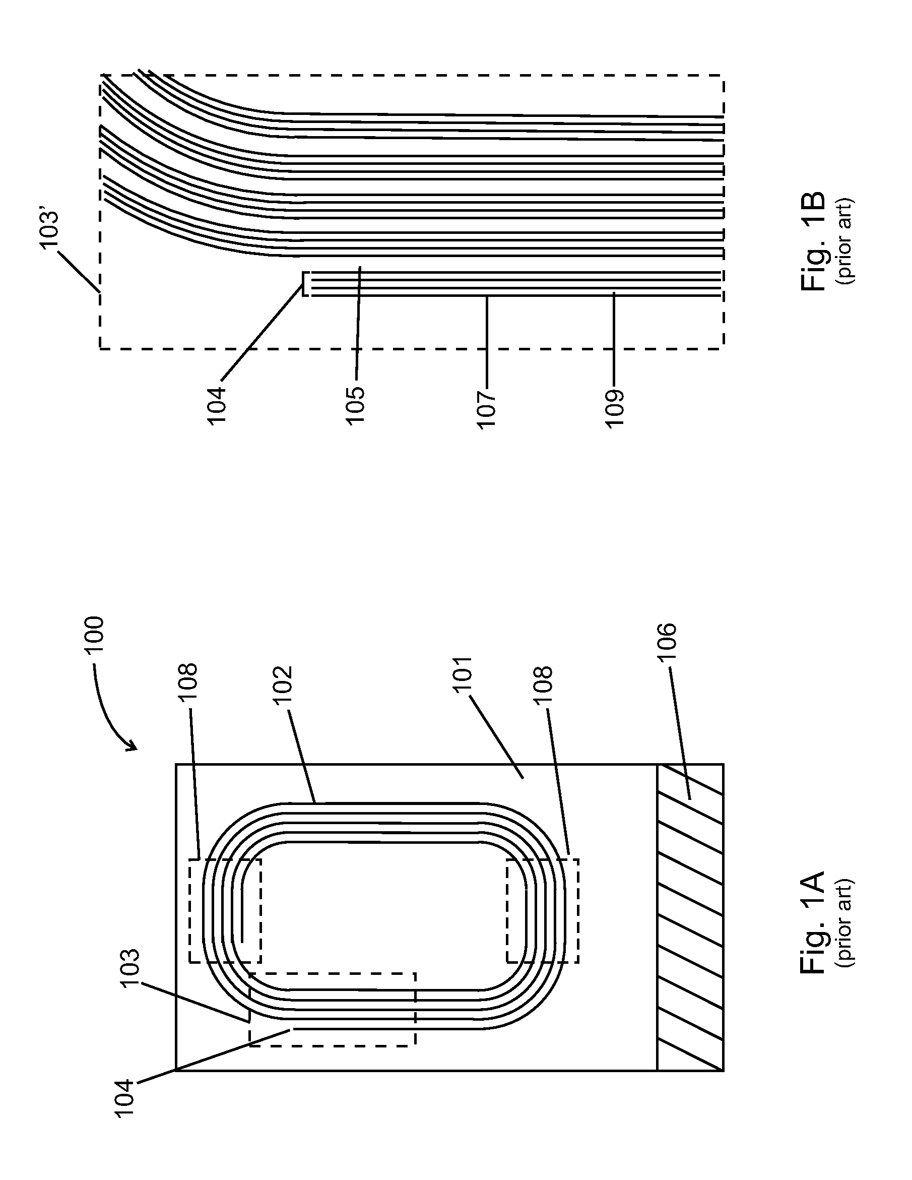
[0030]FIG. 1A depicts a prior art HTS NMR probe coil assembly 100 that provides the RF field to the sample thereby stimulating the nuclear spins and then receiving the response of the nuclear spins in the sample. Typically the coil winding 102 is composed of a high temperature superconducting (HTS) material such as yttrium barium copper oxide (YBCO). The HTS material may be sputtered, evaporated, or otherwise deposited upon an electrically insulating planar substrate 101 such as sapphire. Typically the supporting substrate may be 400 micrometers thick and the HTS material 0.3 micrometers thick. Each turn of the coil may be composed of a number of parallel channels, o...


PUM


Abstract

RF electric fields produced by electric potential differences in NMR probe coil windings may penetrate the NMR sample and sample tube causing sensitivity loss and noise in NMR spectroscopy. Counter-wound spiral coils placed on the opposite surfaces of a planar substrate or on two adjacent planar substrates produce electric potentials that minimize the electric field over the sample region, thereby increasing the sensitivity of the NMR probe. Alternatively counter-wound spiral coils placed adjacent to each other on the outer surface of two concentric cylindrical surfaces that surround the NMR sample minimize the electric field over the sample region. The electric potential of the spiral coils is reduced by adjusting a length of at least one coil.

Description

FIELD OF THE INVENTION[0001]This invention relates to nuclear magnetic resonance (NMR) and in particular to RF probe coil geometries that provide a strong RF magnetic field with a minimum of RF electric field over the sample volume.BACKGROUND OF THE INVENTION[0002]NMR is a powerful technique for analyzing molecular structure. However it is also an insensitive technique compared to others for structure determination. To gain maximum sensitivity, NMR magnets and spectrometers are designed to operate at high magnetic field strengths, employ low noise preamplifiers and RF probe coils that operate at cryogenic temperatures using cold normal metal transmit / receive coils or preferably transmit / receive coils made with high temperature superconducting (HTS) materials. The transmit / receive coils are the probe coils that stimulate the nuclei and detect the NMR response from the sample, and therefore are placed very close to the sample to provide high sensitivity. The HTS coils have the highest...

Claims


Application Information

Patent Timeline
Patent Type & Authority Patents(United States)
IPC IPC(8): G01V3/00
CPCG01R33/3628G01R33/34069G01R33/34053G01R33/34007G01R33/34023G01R33/34092
Inventor WITHERS, RICHARD S.NAST, ROBERT E.ANDERSON, WESTON A.
Owner AGILENT TECH INC
Why Eureka
Try Eureka