Electronic apparatus

a technology of electronic components and heat radiation, applied in the field of electronic devices, can solve the problems of increasing the temperature of coolant in the pump and the tank, and the inability to transfer heat from the electronic component to the coolant in sufficient quantities, and achieve the effect of enhancing the efficiency of heat radiation

Inactive Publication Date: 2010-04-20
FUJITSU LTD
View PDF105 Cites 11 Cited by
  • Summary
  • Abstract
  • Description
  • Claims
  • Application Information

AI Technical Summary

Benefits of technology

[0006]It is accordingly an object of the present invention to provide an electronic apparatus allowing an enhanced efficiency of heat radiation.
[0008]Heat of the electronic component is transferred to the thermal conductive plate of the heat receiver in the electronic apparatus. The heat of the thermal conductive plate is transferred to the coolant flowing through the flow passage. The electronic component gets cooled. The coolant flows into the tank. The tank stores the coolant and air in the closed circulating loop. The air inlet is formed in the enclosure. Fresh air is introduced into the enclosure through the air inlet. Since the tank is opposed to the air inlet, the tank is exposed to the fresh air. The heat of the coolant in the tank is thus radiated into the air. The coolant gets cooled in an efficient manner. The efficiency of heat radiation is enhanced in this manner.
[0009]The electronic apparatus may further comprise: a pump inserted in the closed circulating loop so as to circulate coolant along the closed circulating loop; and an air inlet formed in the enclosure, the air inlet opposed to the pump. Since the pump is opposed to the air inlet, the pump is exposed to fresh air introduced through the air inlet. The heat of the coolant in the pump is thus radiated into the air. The coolant gets cooled in a highly efficient manner. The efficiency of heat radiation is further enhanced in this manner. It should be noted that the air inlet opposed to the tank may be combined with the air inlet opposed to the pump.
[0011]Heat of the electronic component is transferred to the thermal conductive plate of the heat receiver in the electronic apparatus in the same manner as described above. The heat of the thermal conductive plate is transferred to the coolant flowing through the flow passage. The electronic component gets cooled. The coolant flows into the pump. The pump allows circulation of the coolant along the closed circulating loop. The air inlet is formed in the enclosure. Fresh air is introduced into the enclosure through the air inlet. Since the pump is opposed to the air inlet, the pump is exposed to the fresh air. The heat of the coolant in the pump is thus radiated into the air. The coolant gets cooled in an efficient manner. Efficiency of heat radiation is enhanced in this manner.

Problems solved by technology

This results in rise in the temperature of coolant in the pump and the tank.
The heat cannot thus sufficiently be transferred from the electronic component to the coolant.

Method used


Image

  • Electronic apparatus
  • Electronic apparatus
  • Electronic apparatus

Examples


first embodiment

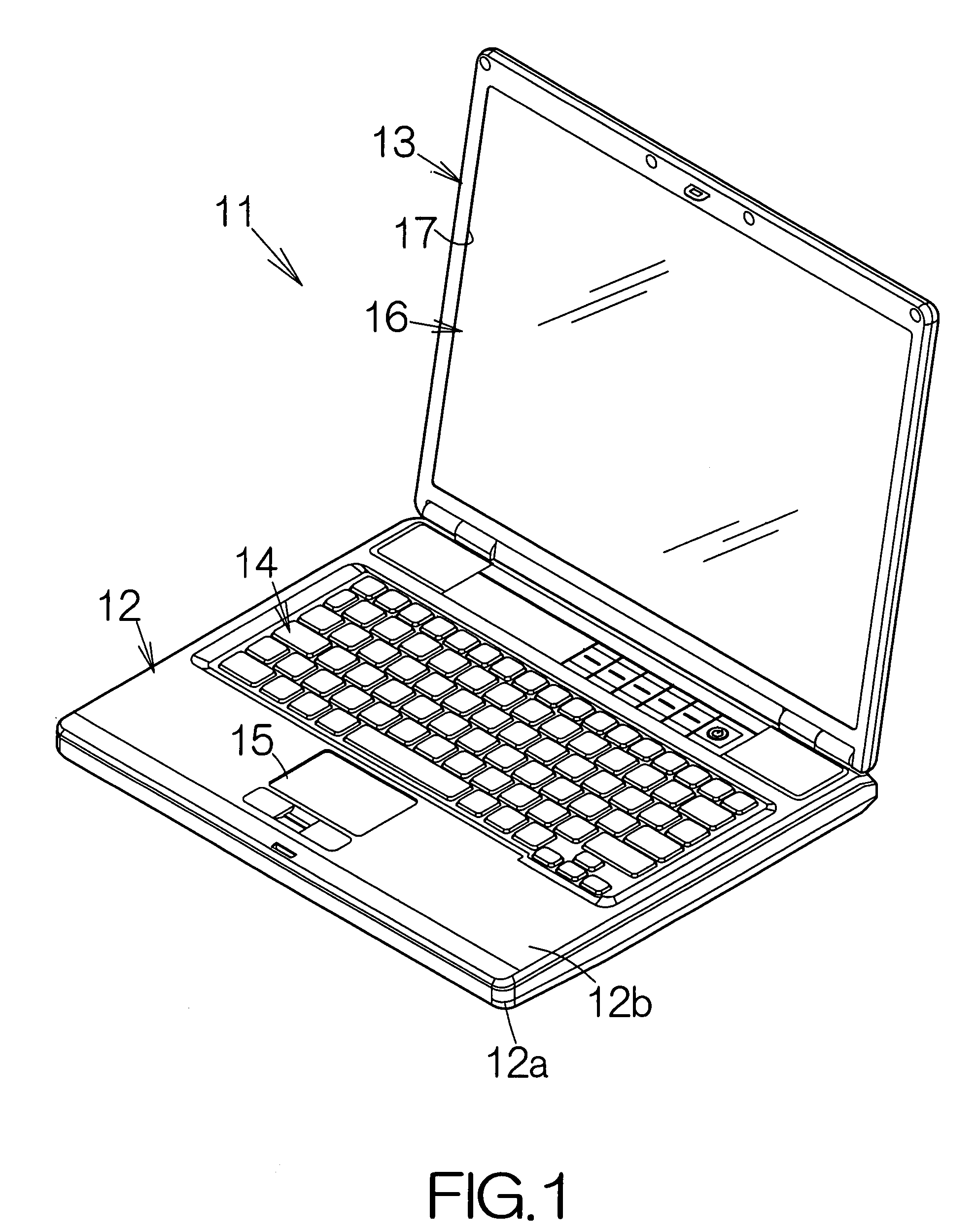
[0032]FIG. 1 schematically illustrates a notebook personal computer 11 as a specific example of an electronic apparatus according to the present invention. The notebook personal computer 11 includes a thin first enclosure, namely a main body enclosure 12, and a second enclosure, namely a display enclosure 13. The display enclosure 13 is coupled to the main body enclosure 12 for relative swinging movement. The main body enclosure 12 includes a base 12a and a cover 12b removably coupled to the base 12a. Input devices such as a keyboard 14 and a pointing device 15 are embedded in the surface of the cover 12b, for example. Users manipulate the keyboard 14 and / or the pointing device 15 to input commands and / or data.

[0033]A liquid crystal display (LCD) panel module 16 is enclosed in the display enclosure 13, for example. The screen of the LCD panel module 16 exposes within a window opening 17 defined in the display enclosure 13. Texts and graphics appear on the screen. Users can see the o...

second embodiment

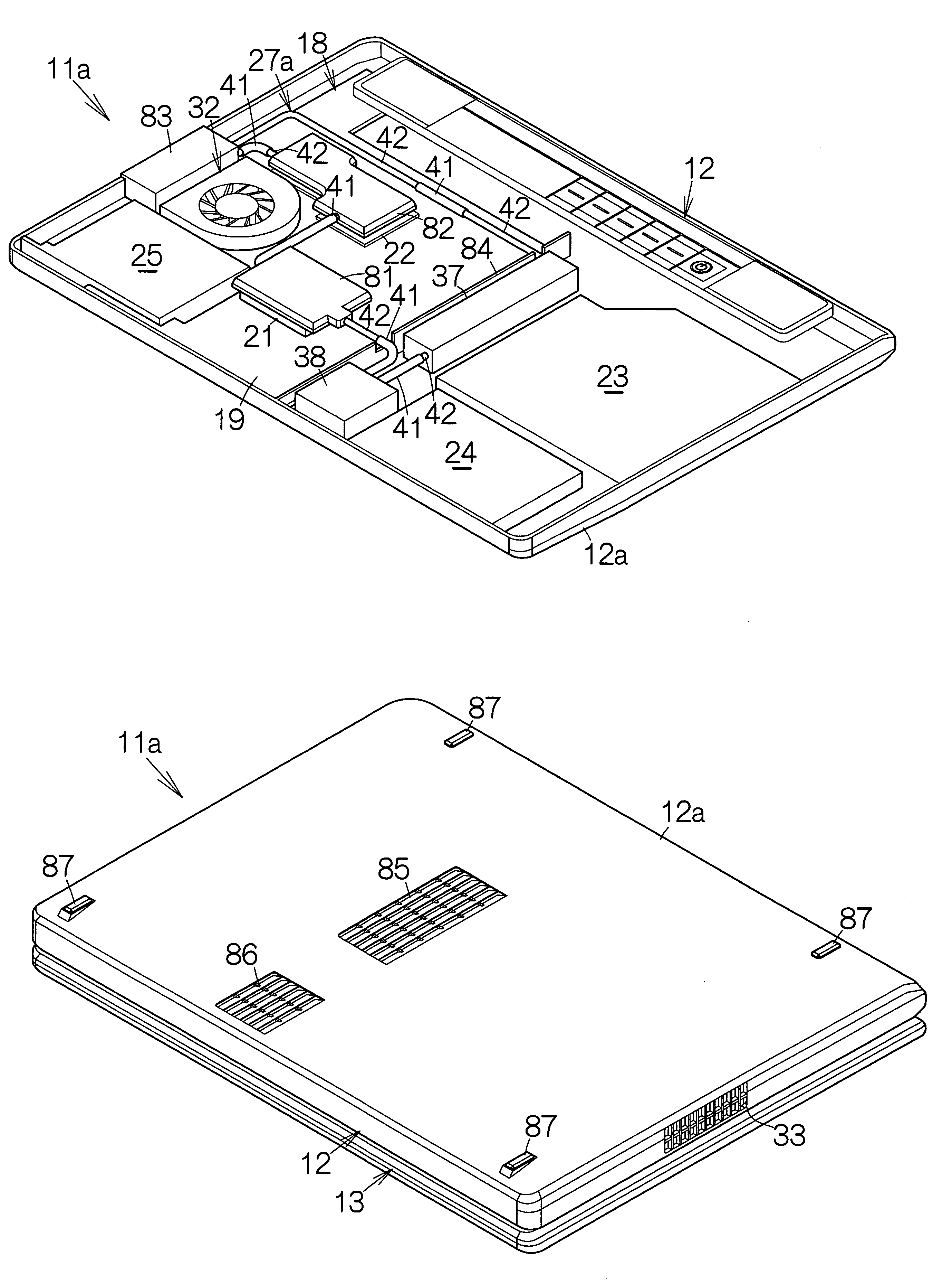
[0077]FIG. 14 schematically illustrates the inner structure of a notebook personal computer 11a as a specific example of an electronic component according to the present invention. The notebook personal computer 11a includes a liquid cooling unit 27a placed in the inner space of the main body enclosure 12. The liquid cooling unit 27a includes a first heat receiver 81, a second heat receiver 82 and a heat exchanger 83 in place of the aforementioned first heat receiver 28, second heat receiver 29 and heat exchanger 31. A closed circulating loop is established in the liquid cooling unit 27a. The first heat receiver 81 is inserted in the closed circulating loop. Like reference numerals are attached to the structure or components equivalent to those of the aforementioned notebook personal computer 11.

[0078]The fan unit 32 of the liquid cooling unit 27a is placed outside the closed circulating loop. The tank 37 and the pump 38 are placed outside the periphery of the printed wiring board 1...


PUM


Abstract

An electronic apparatus includes an enclosure enclosing a liquid cooling unit. The liquid cooling unit includes a heat receiver received on an electronic component. Heat of the electronic component is transferred to the heat receiver. The heat of the heat receiver is transferred to the coolant flowing through the flow passage of the heat receiver. The electronic component gets cooled. The coolant flows into a tank in the liquid cooling unit. The tank stores the coolant and air. The air inlet is formed in the enclosure. Fresh air is introduced into the enclosure through the air inlet. Since the tank is opposed to the air inlet, the tank is exposed to the fresh air. The heat of the coolant in the tank is thus radiated into the air. The coolant gets cooled in an efficient manner. The efficiency of heat radiation is enhanced in this manner.

Description

BACKGROUND OF THE INVENTION[0001]1. Field of the Invention[0002]The present invention relates to an electronic apparatus such as a notebook personal computer, for example.[0003]2. Description of the Prior Art[0004]A printed wiring board is incorporated in an electronic apparatus. An electronic component such as a large-scale integrated circuit (LSI) chip is mounted on the printed wiring board. A liquid cooling unit is placed on the printed wiring board so as to cool the electronic component. The liquid cooling unit includes a closed circulating loop for coolant. A heat receiver such as a liquid cooling jacket is inserted in the closed circulating loop. The heat receiver is received on the electronic component. A pump and a tank are inserted in the closed circulating loop.[0005]The electronic component generates heat during operation. The heat of the electronic component is transferred to the heat receiver and the printed wiring board. The temperature of the printed wiring board thus...

Claims


Application Information

Patent Timeline
Patent Type & Authority Patents(United States)
IPC IPC(8): H05K7/20F28F7/00
CPCG06F1/203F28D1/024F28D15/00F28F3/02F28F3/12F28F13/06H01L2924/0002G06F2200/201H01L2924/00G06F1/1613
Inventor SUZUKI, MASUMIAOKI, MICHIMASATSUNODA, YOSUKEOHNISHI, MASUOHATTORI, MASAHIKO
Owner FUJITSU LTD
Why Eureka
Try Eureka