Multiplex switching

a multi-channel switching and circuit technology, applied in orthogonal multiplex, multiplex communication, electrical devices, etc., can solve the problems of buffer overflow, delay in processing, and difficulty in infinitely increasing the capacity of ram, and achieve the effect of ensuring the number of multiplexing and switching packet data

Inactive Publication Date: 2010-04-20
NEC CORP
View PDF13 Cites 0 Cited by
  • Summary
  • Abstract
  • Description
  • Claims
  • Application Information

AI Technical Summary

Benefits of technology

[0011]It is an object of the present invention to provide a multiplex switching circuit and a multiplex switching method which are capable of readily multiplexing and switching packet data without causing any delay.
[0013]In this way, even when the incoming packet rate exceeds the output throughput, or even when packets are temporarily stored in memory such as RAM for absorbing the excessive rate, multiplexed packets are processed without increasing the processing time and the RAM area for storing the multiplexed packets. Then, packet data can be readily multiplexed and switched without causing any delay.

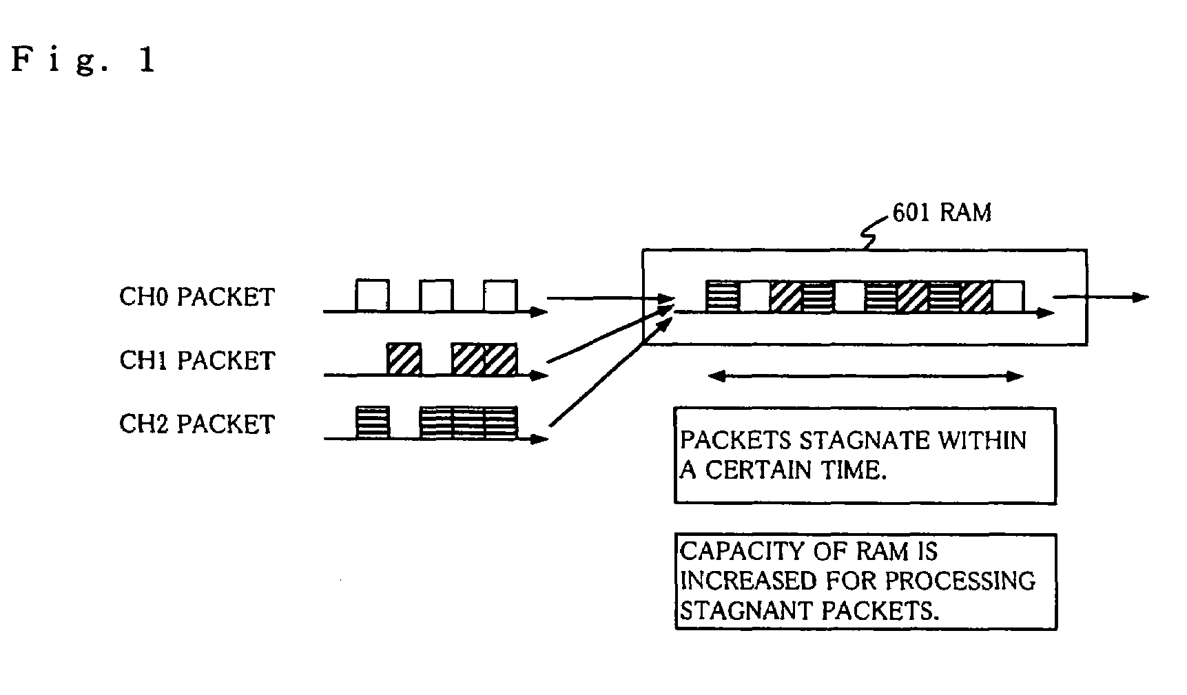
Problems solved by technology

However, when an increased number of channels are supplied at the same time, if a burst of input packets occurs, the packets will stagnate in an internal RAM (buffer) which is used for temporarily storing input packets.
Then, when the stagnation of packets results in a scarcity of RAM area, packets can no longer be stored in the internal RAM, possibly causing a delay in processing, buffer overflow, and the like.
However, it is difficult to infinitely increase the capacity of RAM due to the limitations of price, circuit scale and the like of devices.
However, since the output throughput is determined based on the operation frequency of an internal circuit, it is difficult to infinitely increase the output throughput due to limitations in the operation frequency.
However, although the method disclosed in the foregoing patent document can solve the problem of packet data overflow in the apparatus, there is still a problem that packet data will stagnate in the preceding apparatus, so that the capacity of RAM must be increased in the preceding apparatus.
In addition, since the location in which packet data is stored simply moves from the apparatus of interest to the preceding apparatus, the disclosed method fails to solve a problem of eliminating a delay in data transmission.

Method used


Image

  • Multiplex switching
  • Multiplex switching
  • Multiplex switching

Examples


Embodiment Construction

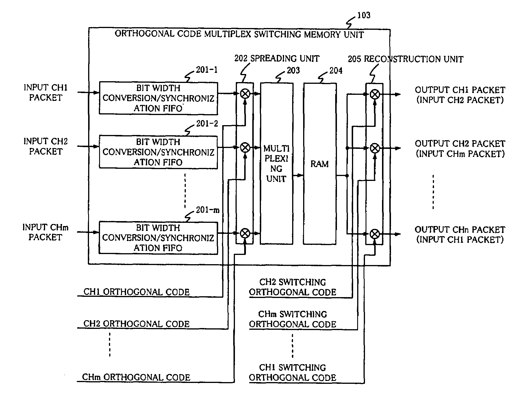
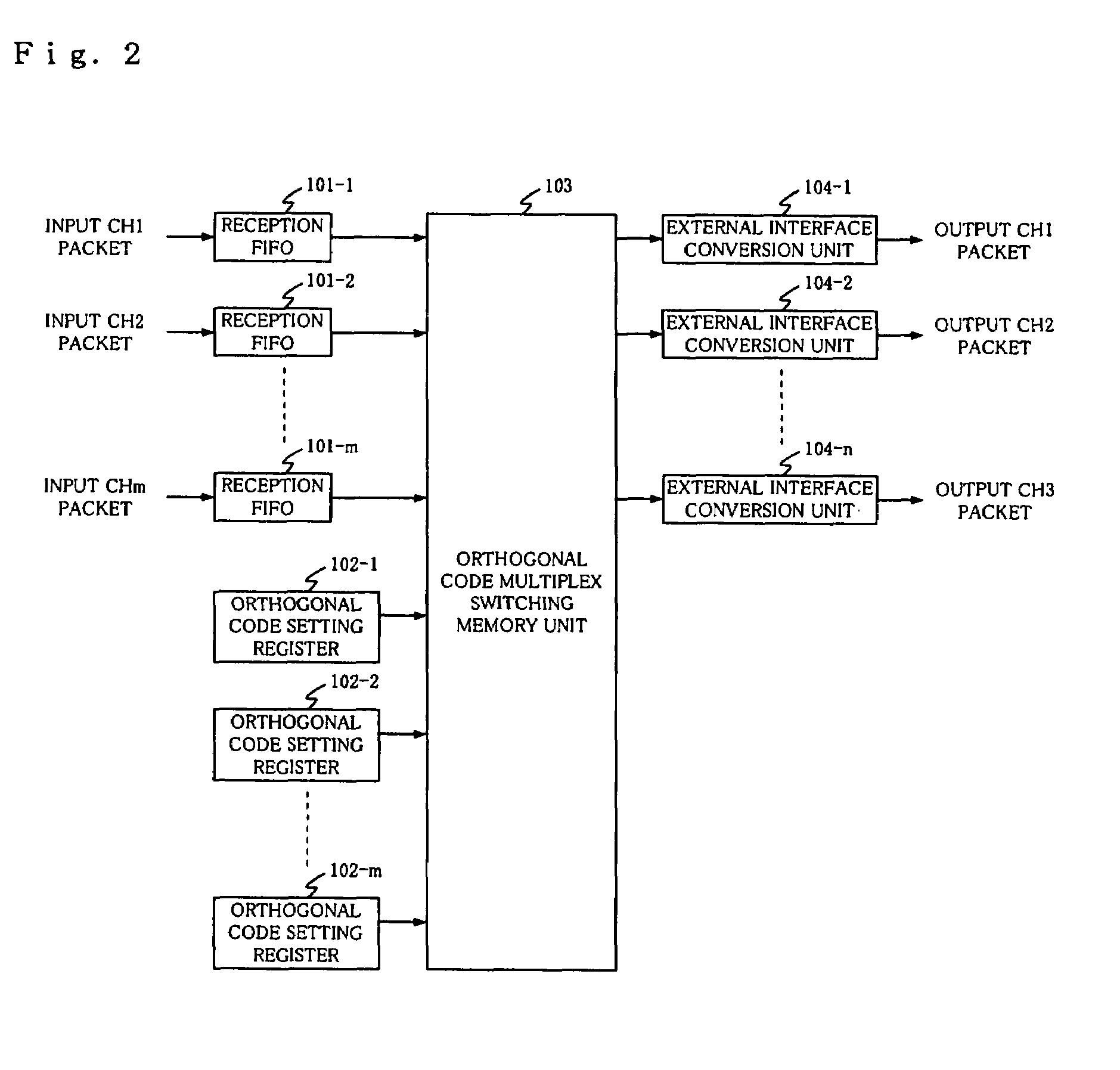
[0021]Referring to FIG. 2, there is illustrated an embodiment of a multiplex switching circuit which comprises reception FIFOs 101-1 to 101-m; orthogonal code setting resisters 102-1 to 102-m; orthogonal code multiplex switching memory unit 103; external interface conversion units 104-1 to 104-n.

[0022]Reception FIFOs 101-1 to 101-m are Fast-In Fast-Out memories each for temporarily storing input packets on channel CH1 to CHm, and for reading the input packets in accordance with the timing of an internal clock in order to synchronize the input packets with the internal clock. Orthogonal code setting registers 102-1 to 102-m are registers each for setting therein an orthogonal code (Gold code, Walsh-Hadamard code or the like) for spreading input packets in corresponding channels, and a orthogonal code for switching for reconstructing output packets in corresponding channels. In this connection, the orthogonal codes and orthogonal codes for switching can be freely set in accordance wi...


PUM


Abstract

Multiplex switching is disclosed for readily multiplexing and switching packet data without causing a delay. Bit widths of packets supplied from a plurality of input channels are unified to a previously set bit width. The packets unified in bit width are synchronized among the plurality of input channels. The synchronized packets are spread by multiplying them by orthogonal codes based on the input channels. The spread packets are multiplexed, and multiplexed packets are multiplied respectively by orthogonal codes for switching according to the input channels on which the packets delivered to output channels have been supplied, to reconstruct the packets supplied from the input channels. The packets are then delivered to the output channels.

Description

BACKGROUND OF THE INVENTION[0001]1. Field of the Invention[0002]The present invention relates to a multiplex switching circuit and a multiplex switching method for multiplexing input packets on a plurality of channels for switching in a base station or the like of a W-CDMA (Wideband-Code Division Multiple Access) radio communications system.[0003]2. Description of the Related Art[0004]Conventionally, in radio communications systems such as a digital portable telephone, a packet transmission apparatus for transmitting packets on a plurality of channels is required to provide high throughput performance for processing a larger amount of small packets supplied thereto at a lower cost. However, when an increased number of channels are supplied at the same time, if a burst of input packets occurs, the packets will stagnate in an internal RAM (buffer) which is used for temporarily storing input packets. Then, when the stagnation of packets results in a scarcity of RAM area, packets can no...

Claims


Application Information

Patent Timeline
Patent Type & Authority Patents(United States)
IPC IPC(8): H04J11/00H04B1/707H04J13/20
CPCH04L49/90H04L49/103H04J13/0003H04B2201/70702
Inventor HORIKOSHI, SHUHEI
Owner NEC CORP
Why Eureka
Try Eureka