Low-voltage oscillator with capacitor-ratio selectable duty cycle

a duty cycle and low-voltage oscillator technology, applied in the direction of oscillator generators, pulse generation by logic circuits, pulse techniques, etc., can solve the problem of quite challenging circuit design for low power supply voltages while the threshold voltage remains around 0.7 volts

Inactive Publication Date: 2010-04-27
HONG KONG APPLIED SCI & TECH RES INST
View PDF7 Cites 11 Cited by
  • Summary
  • Abstract
  • Description
  • Claims
  • Application Information

AI Technical Summary

Problems solved by technology

Designing circuits for low power-supply voltages while the threshold voltages remain around 0.7 volts is quite challenging.

Method used


Image

  • Low-voltage oscillator with capacitor-ratio selectable duty cycle
  • Low-voltage oscillator with capacitor-ratio selectable duty cycle
  • Low-voltage oscillator with capacitor-ratio selectable duty cycle

Examples


Embodiment Construction

[0017]The present invention relates to an improvement in low-voltage oscillators. The following description is presented to enable one of ordinary skill in the art to make and use the invention as provided in the context of a particular application and its requirements. Various modifications to the preferred embodiment will be apparent to those with skill in the art, and the general principles defined herein may be applied to other embodiments. Therefore, the present invention is not intended to be limited to the particular embodiments shown and described, but is to be accorded the widest scope consistent with the principles and novel features herein disclosed.

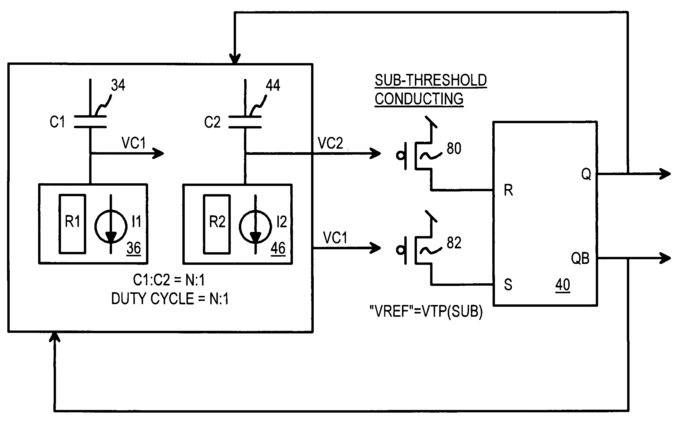
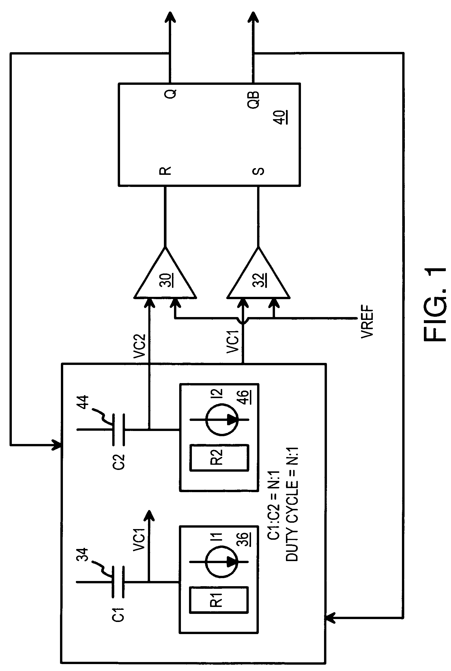
[0018]FIG. 1 is a block diagram of a simplified oscillator with a selectable duty cycle. The output Q and inverse output QB of set-reset S-R latch 40 oscillate when the oscillator is in operation.

[0019]S-R latch 40 toggles output Q high and QB low when its set S input pulses high, which occurs when comparator 32 determines tha...


PUM


Abstract

An oscillator operates at a very low voltage yet has a duty cycle that is set by a ratio of capacitors that are charged and discharged. Sub-threshold p-channel transistors conduct sub-threshold currents below the normal threshold voltage, and drive set and reset inputs of a set-reset S-R latch. The S-R latch drives the oscillator outputs. The oscillator outputs feed back to charging p-channel transistors that charge one plate of the capacitors. During half of the cycle, the charging p-channel transistor is off, allowing one plate of the capacitors to discharge through an n-channel discharge transistor. After a period of discharge determined by the capacitance of the capacitor, the gate of a sub-threshold p-channel transistor falls enough for sub-threshold current to flow, triggering the set or reset input of the S-R latch. Since sub-threshold currents are needed to toggle the S-R latch, the oscillator begins to oscillate below the threshold voltage.

Description

FIELD OF THE INVENTION[0001]This invention relates to oscillator circuits, and more particularly to low-voltage selectable-duty-cycle oscillators.BACKGROUND OF THE INVENTION[0002]Advances in semiconductor processing have resulted in the drastic reduction in device sizes. The gate length of a transistor, meal line widths and spacings, and oxide thicknesses have all undergone a dramatic reduction. However, the voltages applies to these reduced-size transistors must also be reduced to prevent damage to these increasingly tiny devices. Thus the power-supply voltage, such as Vcc or Vdd, has also been reduced from 5 volts to 3.3 volts to 1.8 volts, and now to 1.5 or even 1.2 volts.[0003]While the device sizes have scaled downward, the transistor threshold voltage, Vtn or Vtp, has not scaled down as dramatically. This threshold voltage is now closer to the power-supply voltage than ever before. Designing circuits for low power-supply voltages while the threshold voltages remain around 0.7 ...

Claims


Application Information

Patent Timeline
Patent Type & Authority Patents(United States)
IPC IPC(8): H03B27/00
CPCH03K4/501
Inventor NG, CHIK WAI DAVIDWONG, YAT TO WILLIAMWAN, HO MING KARENKWONG, KWOK KUEN DAVID
Owner HONG KONG APPLIED SCI & TECH RES INST
Why Eureka
Try Eureka