Micro-machined gyrometric sensor for differential measurement of the movement of vibrating masses

a gyrometric sensor and differential measurement technology, applied in the direction of acceleration measurement using interia forces, turn-sensitive devices, instruments, etc., can solve the problems of impairing the proper operation and high cost of fabricating multi-wafer assemblies, and achieve good linearity, high sensitivity, and good bias stability

Active Publication Date: 2010-05-04
THALES SA
View PDF6 Cites 9 Cited by
  • Summary
  • Abstract
  • Description
  • Claims
  • Application Information

AI Technical Summary

Benefits of technology

[0011]One object of the invention is to propose a microgyroscope structure that allows rotation measurement with a very high sensitivity, very good linearity and very good bias stability, but with minimal perturbations due to the excitation movement or to the static or dynamic acceleration applied in the axis collinear with the axis of displacement of the masses. Another object is to propose a microgyroscope structure that can accommodate, apart from the electrical structures for inducing vibration and for detecting movement, auxiliary electrical structures for adjusting the frequency, for compensating for any bias (an angular velocity measurement not equal to zero when the angular velocity is equal to zero) due to intrinsic defects or to the spread in characteristics resulting from mass production and for slaving the position of the masses on a fixed position which may be that which it occupies when the masses are at rest.

Problems solved by technology

To fabricate the multi-wafer assembly is expensive.
When the two masses do not have a perfectly identical static capacitance, the difference in capacitance of the two masses is the cause of a drift of the gyroscope, which impairs its proper operation.

Method used


Image

  • Micro-machined gyrometric sensor for differential measurement of the movement of vibrating masses
  • Micro-machined gyrometric sensor for differential measurement of the movement of vibrating masses

Examples


Embodiment Construction

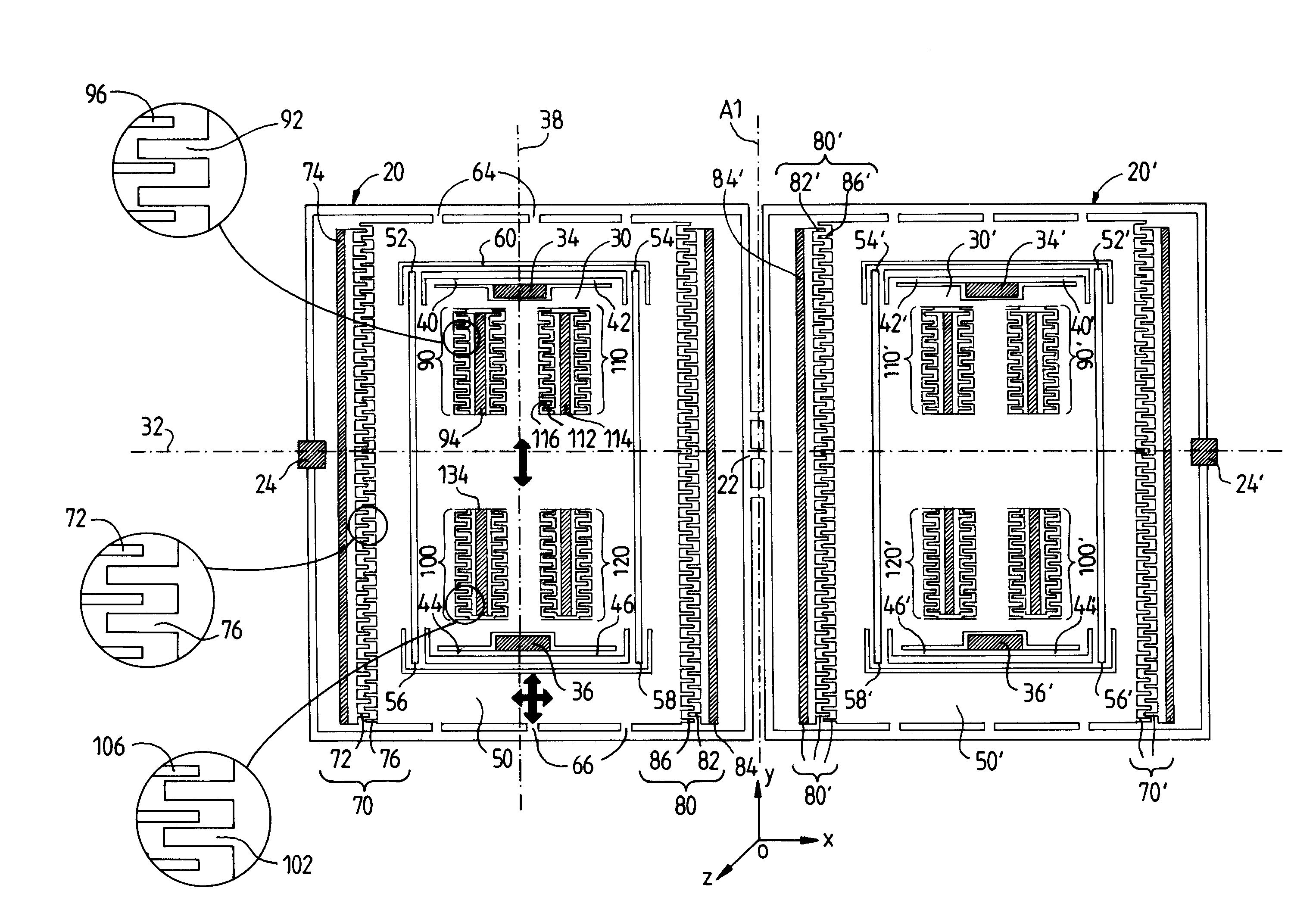
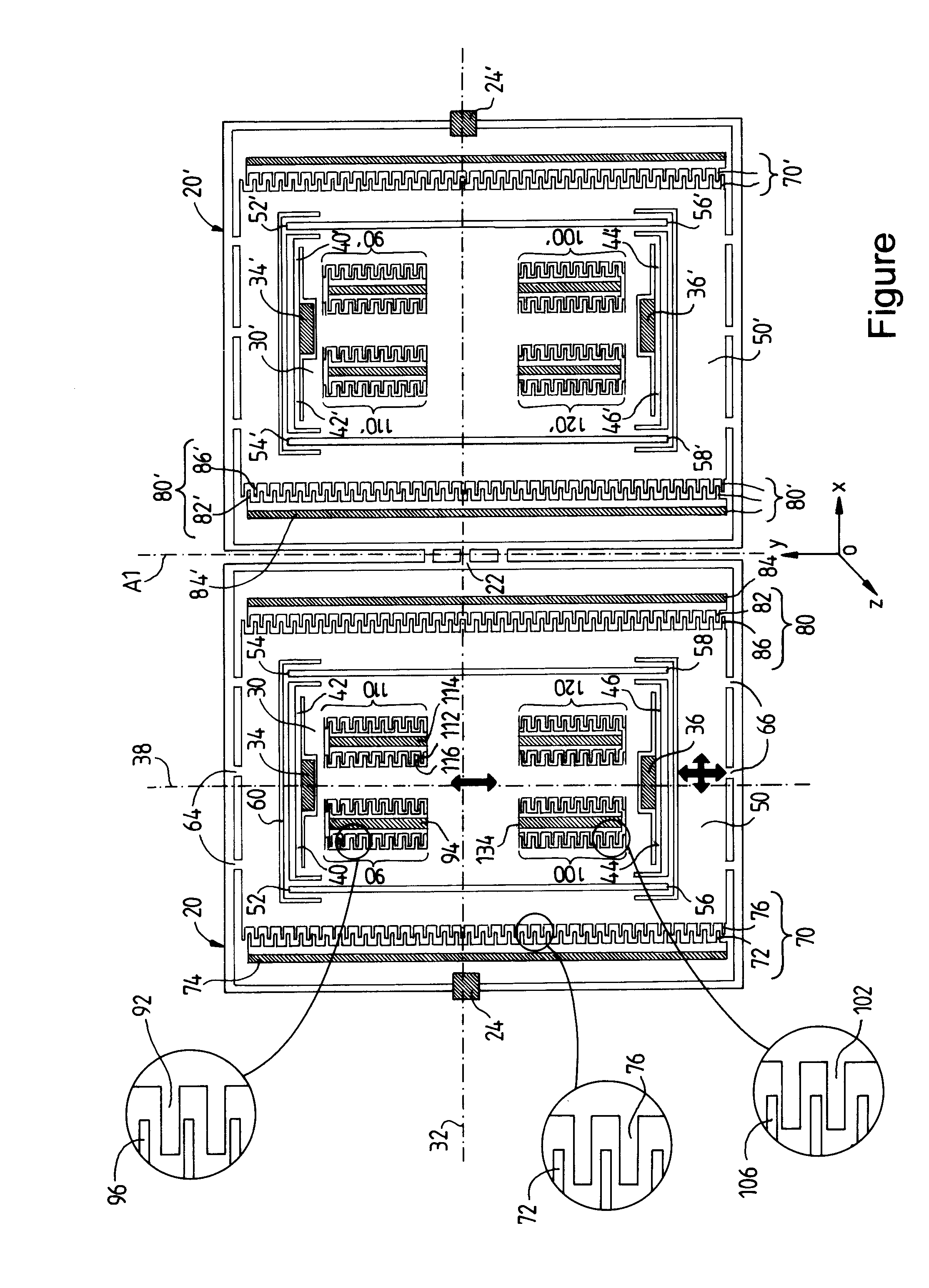
[0015]The FIGURE shows the thin flat silicon wafer machined according to the invention in order to make a gyroscope whose sensitive axis is perpendicular to the plane of the wafer (which is the plane of the FIGURE).

[0016]Silicon is chosen as preferred material, firstly for its mechanical properties and secondly for its high conductivity when it is doped sufficiently with an appropriate impurity (boron in general in the case of p-type silicon). Conductive silicon allows the electrical functions of the gyroscope, and especially the excitation and detection functions, to be carried out. These functions are carried out by interdigitated capacitive combs supplied with electrical current or voltage. The fingers of these combs, machined directly in the conductive silicon, serve as the plates of capacitors useful for the excitation and detection functions.

[0017]The thickness of the starting silicon wafer is a few hundred microns. The wafer has, on the one hand, fixed anchoring regions forme...


PUM


Abstract

The invention relates to a microgyroscope, that is to say an inertial micromechanical sensor dedicated to the measurement of angular velocities, which is produced by micromachining techniques, and has a novel arrangement of the modules for measuring the movement of the vibrating masses. The gyroscope comprises two symmetrical moving assemblies (30, 50; 30′, 50′) that are coupled by a coupling structure (20, 20′, 22). Each of the two assemblies comprises a moving mass (30) surrounded by a moving intermediate frame (50). The frame (50) is connected to the coupling structure (20, 20′, 22) and can vibrate in two degrees of freedom in orthogonal directions Ox and Oy of the plane of the wafer. The mass (30) is connected, on one side, to the frame and, on the other side, to fixed anchoring regions (34, 36) via linking means (40-46; 52-58) that allow the vibration movement in the Oy direction to be transmitted to the mass without permitting any movement of the mass in the Ox direction. An excitation structure (70) is associated with the frame in order to excite its vibration along Ox. A movement detection structure (90) is associated with the mass (30) in order to detect its vibration along Oy.

Description

CROSS REFERENCE TO RELATED APPLICATIONS[0001]The present Application is based on International Application No. PCT / EP2006 / 063306 filed on Jun. 19, 2006, which in turn corresponds to French Application No. 05 07144 filed on Jul. 5, 2005, and priority is hereby claimed under 35 USC §119 based on these applications. Each of these applications are hereby incorporated by reference in their entirety into the present application.[0002]The invention relates to a microgyroscope, that is to say an inertial micromechanical sensor dedicated to the measurement of angular velocities, which is produced by micromachining techniques and has a novel arrangement of the modules for measuring the movement of the vibrating masses.BACKGROUND OF THE INVENTION[0003]The inspiration for micromachining sensors comes from techniques for producing integrated circuits. This consists in producing, collectively on a single thin wafer (in principle a silicon wafer), several tens or hundreds of identical sensors usin...

Claims


Application Information

Patent Timeline
Patent Type & Authority Patents(United States)
IPC IPC(8): G01C19/56G01P9/00G01C19/5747
CPCG01C19/5747
Inventor ROUGEOT, CLAUDECHAUMET, BERNARDLE VERRIER, BERTRANDWILLEMIN, JEROME
Owner THALES SA
Why Eureka
Try Eureka