Circuit arrangement for a photovoltaic system

a photovoltaic system and circuit arrangement technology, applied in the direction of photovoltaics, electric variable regulation, batteries, etc., can solve the problems of loss of photovoltaic system performance, and achieve the effects of improving safety, availability, reliability and maintainability of photovoltaic systems

Inactive Publication Date: 2010-05-04
ROEHRIG RUEDIGER +1
View PDF10 Cites 190 Cited by
  • Summary
  • Abstract
  • Description
  • Claims
  • Application Information

AI Technical Summary

Benefits of technology

[0034]The advantage achieved with the invention compared to the previous method for the control/regulation of photovoltaic systems is a higher performance yield, which is achieved by the simultaneous and quasi-continuous operation of all connected solar

Problems solved by technology

However, differences in the MPP currents of the individual solar generators of a string lead to a loss of perform

Method used


Image

  • Circuit arrangement for a photovoltaic system
  • Circuit arrangement for a photovoltaic system
  • Circuit arrangement for a photovoltaic system

Examples


Embodiment Construction

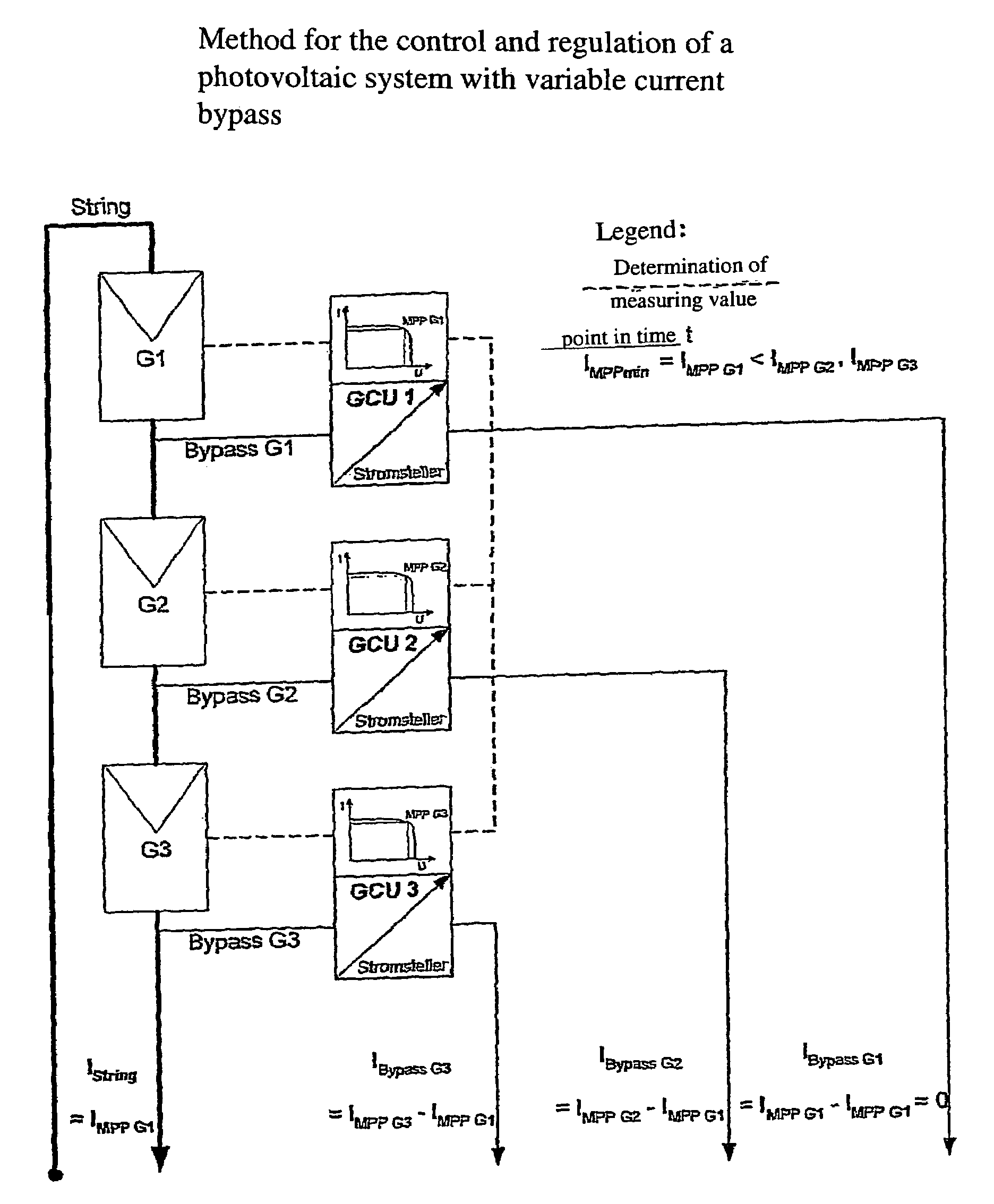
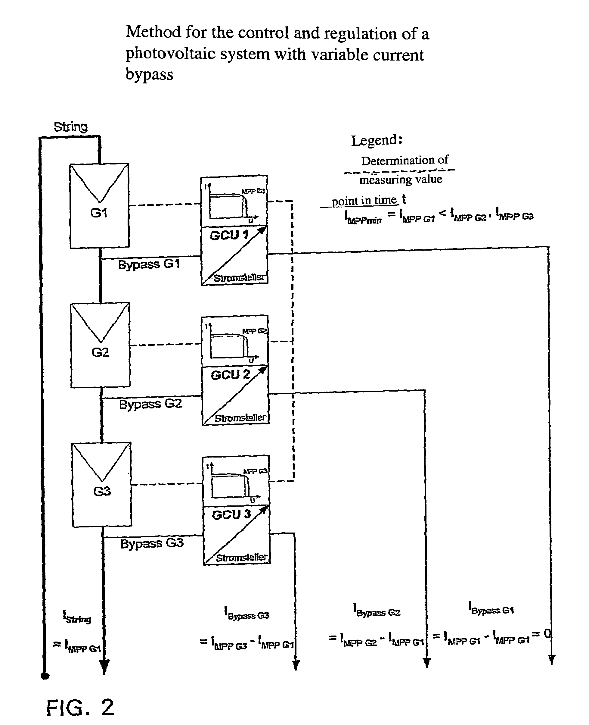
[0052]FIGS. 1 to 3 are used to explain the principle of a bypass control / regulation in a simplified manner.

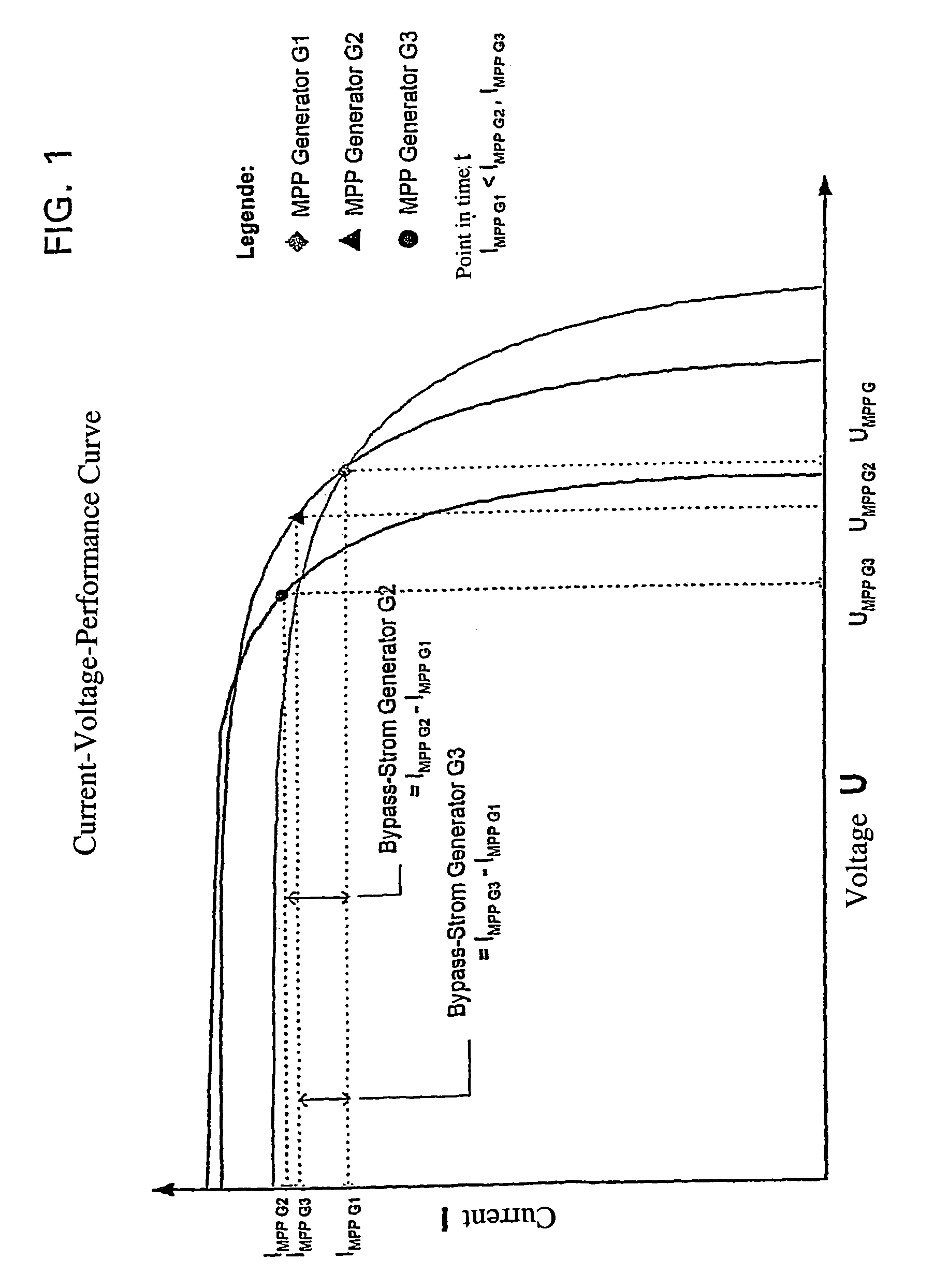
[0053]FIG. 1 shows the current-voltage performance curve of three random generators G1, G2 and G3 at a specific point in time t. In this example, each generator has a specific MPP with the related current- and voltage values (IMPP G1, IMPP G2, IMPP G3 and / or UMPP G1, UMPP G2, UMPP G3), with IMPP G1 being smaller than IMPP G2 and smaller than IMPP G3. If said three generators are connected in series into a string and loaded, a string current of uniform strength flows through all three generators so that at least two generators cannot be operated in their MPP. With the method in accordance with the invention (see FIG. 2) to operate the circuit arrangement in accordance with the invention, the string is loaded such that the string current is exactly the same size as IMPP G1. Bypass currents are branched off from the generators G2 and G3, with the size of said bypass currents at sa...


PUM


Abstract

The invention relates to a circuit arrangement for controlling/regulating photovoltaic systems (10b) which comprise a plurality of solar generators (14b) connected in series or/and connected in parallel. In order to prevent power loss of solar generators, which is based on the fact that not all solar generators are operated in the MPP thereof, each solar generator is associated with a variable energy bypass (68b) that is controlled/regulated in such a manner that each solar generator (14b) is operated continuously in its respective current specific MPP.

Description

CROSS REFERENCE TO RELATED APPLICATION[0001]This application is a 35 USC §371 National Phase Entry Application from PCT / DE03 / 01611, filed May 19, 2003, and designating the U.S.BACKGROUND OF THE INVENTION[0002]1. Field of the Invention[0003]The invention relates to a circuit arrangement for controlling / regulating photovoltaic systems that comprise a plurality of solar generators connected in series and / or in parallel.[0004]2. Description of Related Art[0005]It is generally known that photovoltaic solar generators perform optimally only if the generator is operated at a specific operating point, i.e., the maximum power point, which is referred to as MPP in the following. With each generator, the MPP depends on the respective external operating conditions, in particular the current radiation intensity and the temperature as well as the condition of the generator itself, in particular as a condition of production tolerances, age, defects, contaminations, etc. For these reasons, each gen...

Claims


Application Information

Patent Timeline
IPC IPC(8): H01L31/00H01L25/00G05F1/67H02J3/38H01L27/142H01L31/042H02J4/00
CPCH01L31/02021Y10S136/293Y02E10/50
Inventor ROEHRIG, RUEDIGERSTEGER, JOSEF
Owner ROEHRIG RUEDIGER
Why Eureka
Try Eureka