Terahertz detector

a detector and terahertz technology, applied in the field of electromagnetic radiation detection, can solve the problems of large and expensive pulsed lasers, cryogenic cooling, and complicated use of pulsed lasers, and achieve the effect of greater signal to noise ratio and greater sensitivity

Active Publication Date: 2010-05-04
UNIVERSITY OF ESSEX +1
View PDF3 Cites 3 Cited by
  • Summary
  • Abstract
  • Description
  • Claims
  • Application Information

AI Technical Summary

Benefits of technology

[0010]The preferred embodiment is to use a high bandwidth electroabsorption modulator connected to a high frequency antenna and a small DC reverse bias voltage. In this preferred embodiment the modulator does not need to be cryogenically cooled. The preferred approach used here is to use an antenna to apply the THz signal across the contacts of an electroabsorption modulator to achieve higher electric fields across the multiple quantum well absorber region due to the THz signal. The detection approaches outlined do not need pulsed lasers (although they may be compatible with them if required) and may use either fibre coupled devices or planar optical waveguides to transmit the optical signal between components to give a more compact system. Thus, the laser light source may be a continuous wave laser light source. Within the optical modulator light may propagate along the plane of the device to give a higher overlap of the optical and THz fields and consequently a stronger detected signal.
[0012]If the amount of THz radiation coupled into the antenna is relatively low (for example approximately 1 μW) then a more sensitive detection approach is to heterodyne the optical signal emerging from the modulator with another optical wave. A balanced detector may then be used to enhance sensitivity.

Problems solved by technology

Whilst THz systems have been constructed they generally use large and expensive pulsed lasers to generate pulsed THz radiation.
While several techniques have been put forward for detecting THz radiation, such as electro-optic sampling, photoconductive sampling and use of bolometers, they are complicated by the need for the pulsed lasers and / or cryogenic cooling.

Method used


Image

  • Terahertz detector
  • Terahertz detector
  • Terahertz detector

Examples


example 1

[0029]If the DC transfer characteristics are similar to an existing modulator design ((dT / dV)^2) / T0˜0.5) and the power out of laser 1 is 10 mW, then assuming representative values of Rωt˜0.01, Vp˜0.01V (corresponding to a 1 μW absorbed THz radiation in a 50Ω antenna), R˜0.8 A / W and Δf˜50 MHz then the expected S / N ratio is approximately 21 dB.

example 2

[0030]Sensitivity can be greatly improved through use of a narrower electrical filter to reduce Δf if the laser wavelengths can be controlled with enough precision and their linewidths are narrow enough.

[0031]For example if the laser was sufficiently stable and narrow linewidth to permit operation with a 1 kHz electrical filter (to allow sampling at up to 1 kHz) then if the same parameters as in Example 1 are used the expected S / N ratio is approximately 68 dB. This S / N ratio and sample rate are thought to exceed current state of the art systems.

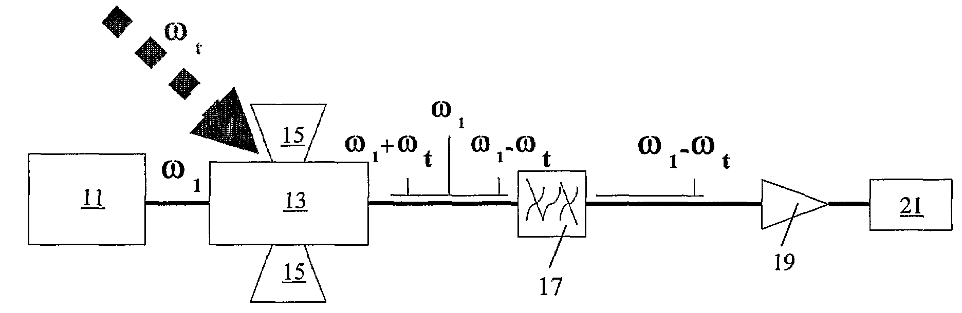
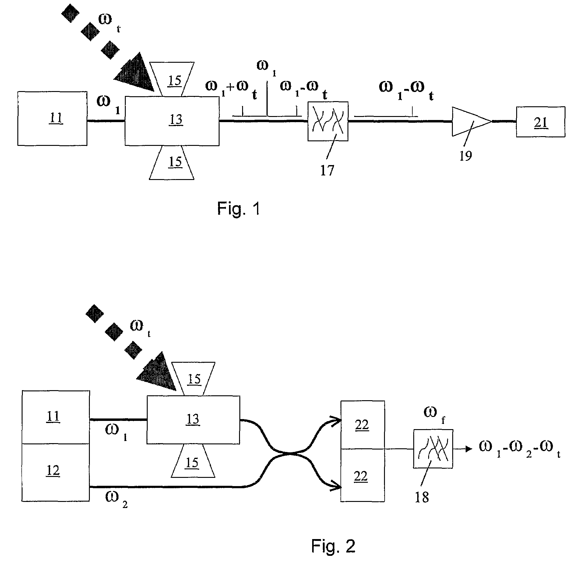
[0032]In summary, a detector for electromagnetic radiation in the range 80 GHz to 4 THz comprises a laser light source 11, an optical modulator 13 arranged to modulate light from the laser light source 11 and a filter system 17 for selecting a defined range of frequencies of the modulated light. The optical modulator is an electroabsorption modulator 13 with an antenna 15 which is sensitive to electromagnetic radiation in the range 80 GHz to ...


PUM


Abstract

A detector for electromagnetic radiation in the range 80 GHz to 4 THz comprises a laser light source (115) an optical modulator (13) arranged to modulate light from the laser light source (11) and a filter system (17) for selecting a defined range of frequencies of the modulated light. The optical modulator is an electroabsorption modulator (13) with an antenna (15) which is sensitive to electromagnetic radiation in the range 80 GHz to 4 THz. The signal received by the antenna (15) modulates the electric field across the electroabsorption modulator (13), whereby to modulate the light from the laser light source (11).

Description

[0001]This application is a national phase of International Application No. PCT / GB2006 / 001846 filed May 18, 2006 and published in the English language.FIELD OF THE INVENTION[0002]This invention relates to the detection of electromagnetic radiation in the 80 GHz to 4 THz range.BACKGROUND TO THE INVENTION[0003]The present invention relates to the detection of electromagnetic radiation in the 80 GHz to 4 THz range. This region of the electromagnetic spectrum has potential for a wide range of medical, pharmaceutical and communications commercial applications as well as being scientifically useful across a wide variety of research fields. Whilst THz systems have been constructed they generally use large and expensive pulsed lasers to generate pulsed THz radiation. While several techniques have been put forward for detecting THz radiation, such as electro-optic sampling, photoconductive sampling and use of bolometers, they are complicated by the need for the pulsed lasers and / or cryogenic...

Claims


Application Information

Patent Timeline
Patent Type & Authority Patents(United States)
IPC IPC(8): G01J5/02G01J3/42
CPCG01J3/42
Inventor MOODIE, DAVID GRAHAMROBERTSON, MICHAEL JAMESHENNING, IAN DOUGLAS
Owner UNIVERSITY OF ESSEX
Why Eureka
Try Eureka