Devices in miniature for interferometric use and fabrication thereof

a technology of electronic devices and miniatures, applied in the field of miniature electronic devices and fabrication, can solve the problems of difficult scanning mirror characteristics, heavy weight and bulky interferometers using the fourier transform principl

Inactive Publication Date: 2010-05-04
BOARD OF RGT THE UNIV OF TEXAS SYST
View PDF8 Cites 16 Cited by
  • Summary
  • Abstract
  • Description
  • Claims
  • Application Information

AI Technical Summary

Problems solved by technology

Most current interferometers using a Fourier transform (FT) principle are heavy and bulky.
While various micro-fabrication approaches have been tried in order to create smaller-sized devices, when preparing such a device in miniature, the characteristics of a scanning mirror are challenging (e.g., in terms of stroke, position sensing, and mirror assembly) and have not been suitably met because micro-machined actuators do not generate sufficient stroke and precision position control has not matured sufficiently.

Method used


Image

  • Devices in miniature for interferometric use and fabrication thereof
  • Devices in miniature for interferometric use and fabrication thereof
  • Devices in miniature for interferometric use and fabrication thereof

Examples


Embodiment Construction

[0023]Although making and using various embodiments of the present invention are discussed in detail below, it should be appreciated that the present invention provides many inventive concepts that may be embodied in a wide variety of contexts. The specific aspects and embodiments discussed herein are merely illustrative of ways to make and use the invention, and do not limit the scope of the invention.

[0024]In the description which follows like parts may be marked throughout the specification and drawing with the same reference numerals, respectively. The drawing figures are not necessarily to scale and certain features may be shown exaggerated in scale or in somewhat generalized or schematic form in the interest of clarity and conciseness.

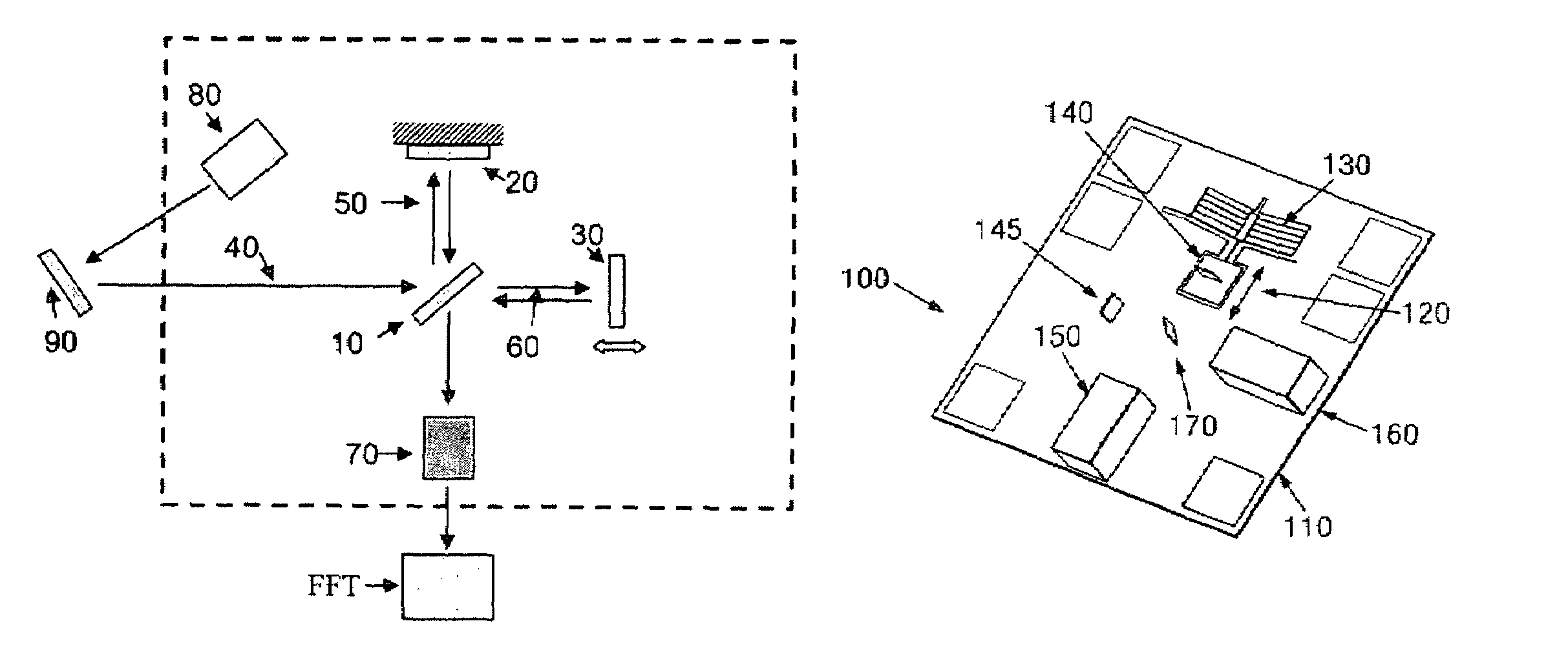
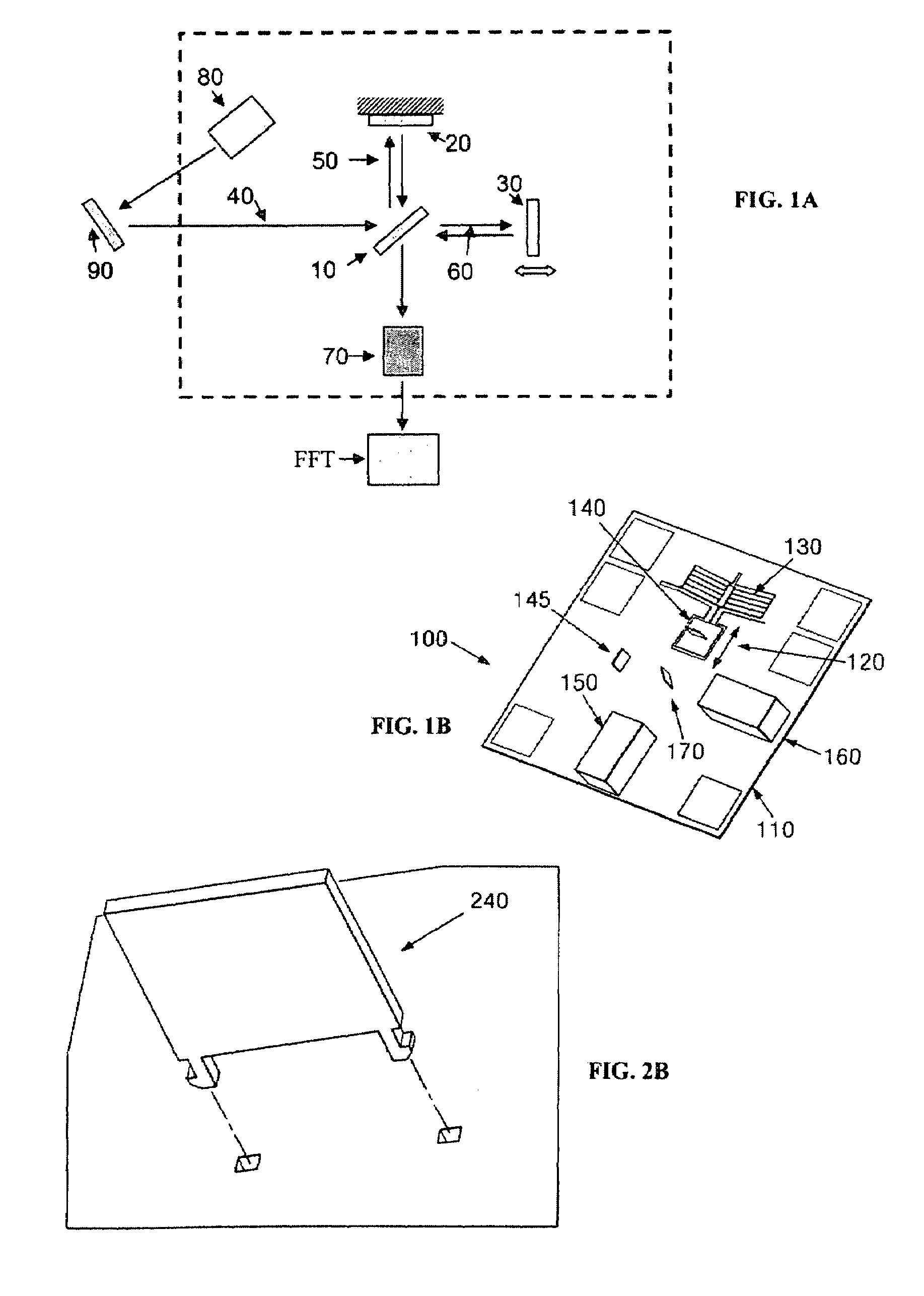
[0025]Optical components such as mirrors and a beam splitter that must be machined and assembled into the smaller device are typically problematic due to misalignments from assembly tolerances that then degrade the quality of spectrum. Previously...


PUM

PropertyMeasurementUnit
lengthaaaaaaaaaa
reflection areaaaaaaaaaaa
tilt anglesaaaaaaaaaa

Abstract

A device in miniature and fabrication of such a device for interferometric use is described, the device including a substrate with at least one deep reactive ion etching structure on at least one surface of the substrate forming an optical bench. The optical bench preferably comprises a moving stage, an actuator, one or more connector sockets and one or more optical components.

Description

CROSS-REFERENCES TO RELATED APPLICATIONS[0001]This application claims the benefit for priority from U.S. Provisional Application No. 60 / 881,939 filed Jan. 23, 2007.BACKGROUND OF THE INVENTION[0002]The invention described relates to the field of electronics and optics, and more specifically to miniaturized electronic devices and fabrication of such a device, such as micro-opto-electro-mechanical systems (MOEMS).[0003]Most current interferometers using a Fourier transform (FT) principle are heavy and bulky. While various micro-fabrication approaches have been tried in order to create smaller-sized devices, when preparing such a device in miniature, the characteristics of a scanning mirror are challenging (e.g., in terms of stroke, position sensing, and mirror assembly) and have not been suitably met because micro-machined actuators do not generate sufficient stroke and precision position control has not matured sufficiently.SUMMARY OF THE INVENTION[0004]The invention described solves ...

Claims


Application Information

Patent Timeline
Patent Type & Authority Patents(United States)
IPC IPC(8): G01J3/45
CPCG01J3/02G01J3/0256G01J3/4532Y10T29/49945G02B26/0833G01J2003/4534
Inventor SIN, JEONGSIKLEE, WOO HO
Owner BOARD OF RGT THE UNIV OF TEXAS SYST
Why Eureka
Try Eureka