Compact mid-ir laser

a laser and mid-infrared technology, applied in semiconductor lasers, instruments, lenses, etc., can solve the problems of limited actual application of mir lasers, hampered, limited auger recombination, etc., and achieve enhanced cooling techniques, high integration and packaging, and light weight

Inactive Publication Date: 2010-09-30
DAYLIGHT SOLUTIONS
View PDF99 Cites 28 Cited by
  • Summary
  • Abstract
  • Description
  • Claims
  • Application Information

AI Technical Summary

Benefits of technology

[0026]The MIR laser device, in accordance with principles of embodiments of the invention, is very compact and light weight, and uses a quantum cascade laser as the laser gain medium. The quantum cascade laser may be selected for the particular application of interest within the frequency range of 3-12 μm by appropriate selection of the thickness of quantum wells and barriers. Such a compact, MIR laser enables a number of instruments to be developed in the fields of medical diagnostics (e.g., on humans and other subjects), homeland security (e.g., on humans or devices), and industrial processing, and other applications based on laser absorption spectroscopy for molecular detection. For example, the beam from a compact handheld MIR laser according to several embodiments described herein can be directed (e.g., aimed or pointed) towards a target (e.g. a living being, an internal organ in the human or animal body, inanimate objects, leaking gases, containers containing chemicals, etc.) located exterior to the MIR laser. The directed beam can intersect with the target and form an infra-red or a thermal image of the target which can be viewed with thermal imaging systems. In some embodiments, intersection of the laser beam with the target can result in the beam being absorbed by the target, or reflected by the target, or scattered by the target, or redirected by the target. Important characteristics of the MIR device is the use of a quantum laser as the laser gain media, short focal length aspheric lens, enhanced cooling techniques that do not require liquid nitrogen and the use of high integration and packaging. The resulting structure presents a foot print that is extremely small with a package size (housing size) of approximately 20 cm (height)×20 cm (width)×20 cm (length) or less. The length is taken along the optical axis. The packages size may be any integer or fraction thereof between approximately 1-20 cm for the length dimension combined with any integer or fraction thereof between approximately 1-20 cm in width dimension combined with any integer or fraction thereof between approximately 1-20 cm in the height dimension. A preferred footprint is approximately 3 cm (height)×4 cm (width)×6 cm (length) for the laser package.
[0027]Some advantages of the MIR device according to embodiments of the invention include high brightness with diffraction limited spatial properties and a narrow spectral width (<100 MHz=0.003 cm-1). The quantum laser gain medium enables high output power (50 mW) and allows easy modulation at high frequency with very low chirp. The packaging technology is mechanically and environmentally robust with excellent thermal properties and provides for dramatic miniaturization.

Problems solved by technology

Actual application of MIR lasers has been more limited and hampered by bulky size and cost of these devices.
While Type II QCLs have demonstrated room temperature CW operation between 3.3 and 4.2 μm, they are still limited by Auger recombination.

Method used


Image

  • Compact mid-ir laser
  • Compact mid-ir laser
  • Compact mid-ir laser

Examples


Embodiment Construction

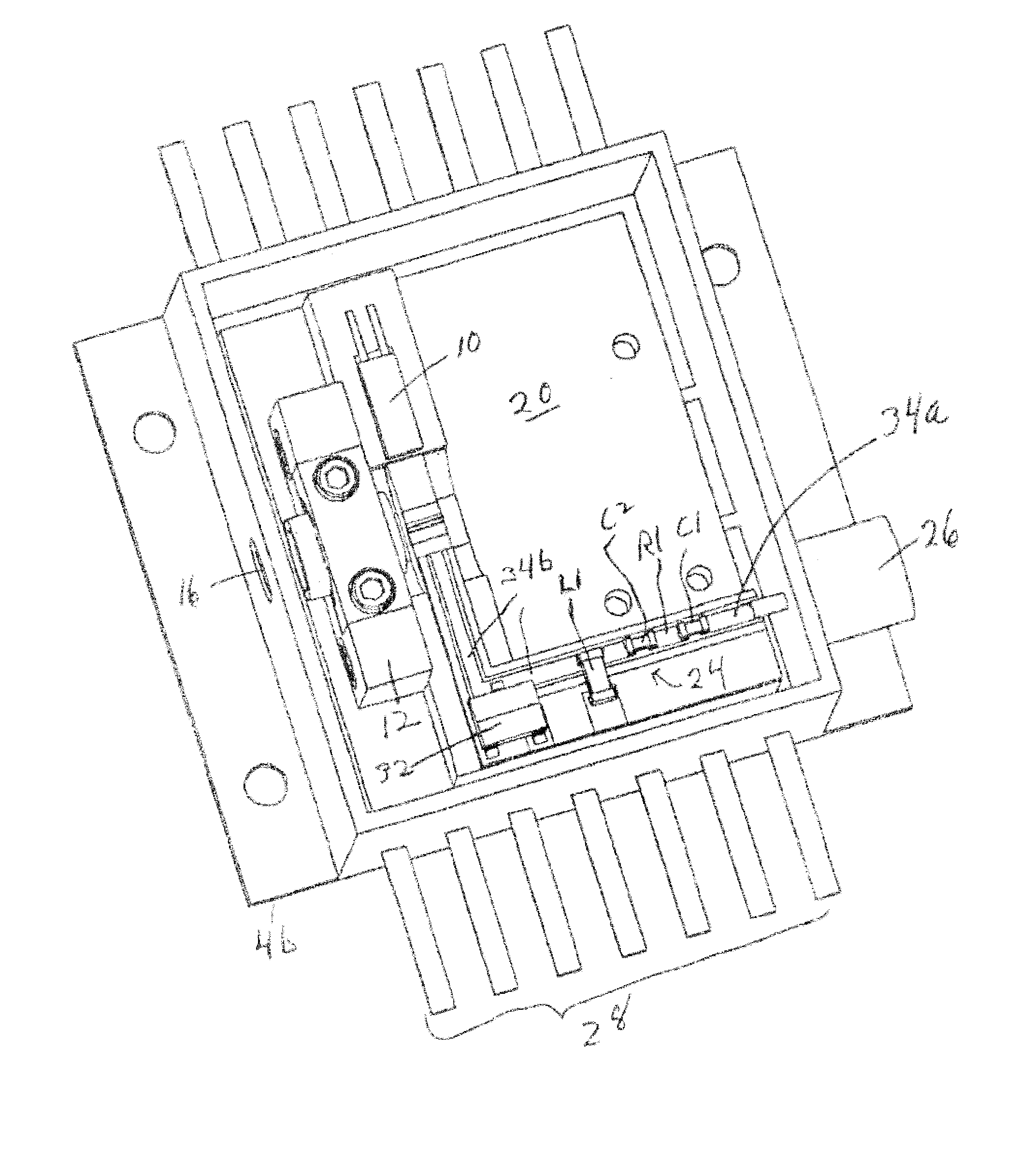
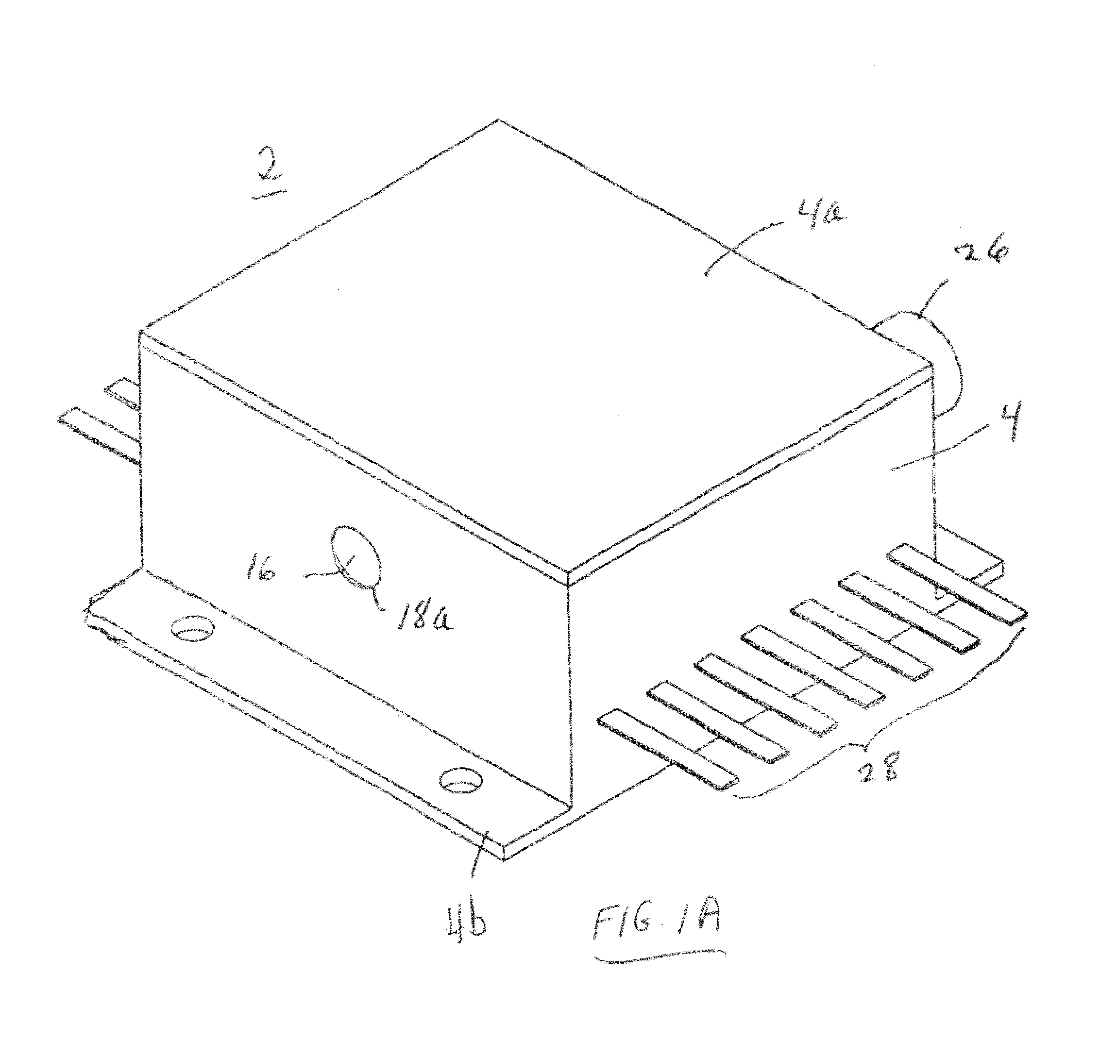
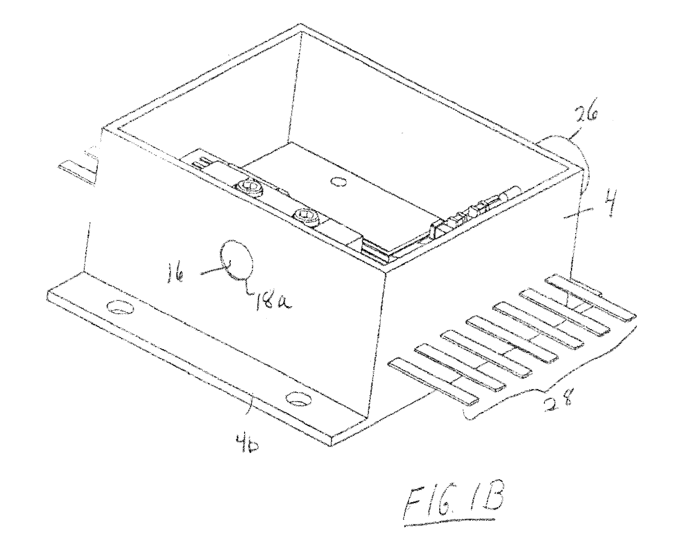
[0041]FIGS. 1A-1C show perspective views of a MIR laser device 2 in accordance with a first embodiment of the invention. FIG. 1A shows the MIR laser device 2 with the housing 4 including the lid or top cover plate 4a and mounting flanges 4b. FIGS. 1B and 1C show the MIR laser device 2 with the lid 4a removed, thus exposing the interior components. FIGS. 2A and 2B show exploded perspective, views of the various components of the MIR laser. FIGS. 3 and 4A show plan and side views respectively of the laser device and FIG. 4B shows an enlarged portion of FIG. 4A.

[0042]As may be seen from these figures, the MIR laser device is seen to include a laser gain medium 6 mounted on a high thermal conductivity sub-mount 8. There is further provided a temperature sensor 10, a lens holder 12, lens mount 13, output lens 14, and window 16. An output aperture 18a is provided in the side of the housing 4 with the window positioned therein. The MIR laser device is also comprised a heat spreader 20, coo...


PUM


Abstract

A compact mid-IR laser device utilizes a quantum cascade laser to provide mid-IR frequencies suitable for use in molecular detection by signature absorption spectra. The compact nature of the device is obtained owing to an efficient heat transfer structure, the use of a small diameter aspheric lens and a monolithic assembly structure to hold the optical elements in a fixed position relative to one another. The compact housing size may be approximately 20 cm×20 cm×20 cm or less. Efficient heat transfer is achieved using a thermoelectric cooler TEC combined with a high thermal conductivity heat spreader onto which the quantum cascade laser is thermally coupled. The heat spreader not only serves to dissipate heat and conduct same to the TEC, but also serves as an optical platform to secure the optical elements within the housing in a fixed relationship relative on one another. A small diameter aspheric lens may have a diameter of 10 mm or less and is positioned to provided a collimated beam output from the quantum cascade laser. The housing is hermetically sealed to provide a rugged, light weight portable MIR laser source.

Description

CROSS-REFERENCE TO RELATED APPLICATIONS[0001]This application is a continuation-in-part of U.S. application Ser. No. 12 / 354,237 filed Jan. 15, 2009, and entitled “COMPACT MID-IR LASER,” which is a continuation of U.S. application Ser. No. 11 / 154,264 filed on Jun. 15, 2005, and entitled “Compact Mid-IR Laser,” now U.S. Pat. No. 7,492,806. The disclosures of each of the above patent applications are hereby incorporated herein by reference in their entirety.BACKGROUND OF THE INVENTION[0002]1. Field of the Invention[0003]Embodiments of the invention relate to a compact Mid-Infrared (MIR) laser which finds applications in many fields such as, molecular detection and imaging (e.g., thermal) instruments for use in medical diagnostics, pollution monitoring, leak detection, analytical instruments, homeland security (e.g., weapon guidance, explosive detectors, thermal detection of objects and individuals, etc.) and industrial process control. Embodiments of the invention are also directed mor...

Claims


Application Information

Patent Timeline
Patent Type & Authority Applications(United States)
IPC IPC(8): H01L31/00H01S5/34H01S3/10H01S3/04
CPCB82Y20/00H01S5/3401G02B6/4201G02B7/023H01S3/1055H01S5/005H01S5/02216H01S5/0222H01S5/02288H01S5/02415H01S5/02476H01S5/028H01S5/0427H01S5/0612H01S5/06226H01S5/141G02B3/00G02B6/4266H01S5/02253
Inventor DAY, TIMOTHYARNONE, DAVID F.
Owner DAYLIGHT SOLUTIONS
Why Eureka
Try Eureka