Adjusting and correcting method of light path of photoelectric system tracking-pointing precision measuring device

A technology of precision measurement and photoelectric system, applied in the direction of measuring devices, optical instrument testing, television, etc., can solve the problems of high sensitivity, unusable, unsuitable for high-precision measurement, etc., and achieve the effect of high precision and simple operation

Active Publication Date: 2018-06-12
西安应用光学研究所
View PDF8 Cites 28 Cited by
  • Summary
  • Abstract
  • Description
  • Claims
  • Application Information

AI Technical Summary

Problems solved by technology

The four-quadrant detector method has high sensitivity. Because the laser spot of the photoelectric system is usually not a uniformly distributed rectangular spot, the output value of the four-quadrant differential amplification and the position of the laser spot are nonlinear, which is not suitable for high-precision measurement.
This method only involves the adjustment of the focal plane of the collimator, and cannot be used for the adjustment of the target plane of the high-frame-rate CCD camera in the tracking and aiming accuracy measurement device of the space laser communication system.

Method used


Image

  • Adjusting and correcting method of light path of photoelectric system tracking-pointing precision measuring device
  • Adjusting and correcting method of light path of photoelectric system tracking-pointing precision measuring device
  • Adjusting and correcting method of light path of photoelectric system tracking-pointing precision measuring device

Examples


Embodiment Construction

[0019] The present invention will be further described below in conjunction with the accompanying drawings and preferred embodiments.

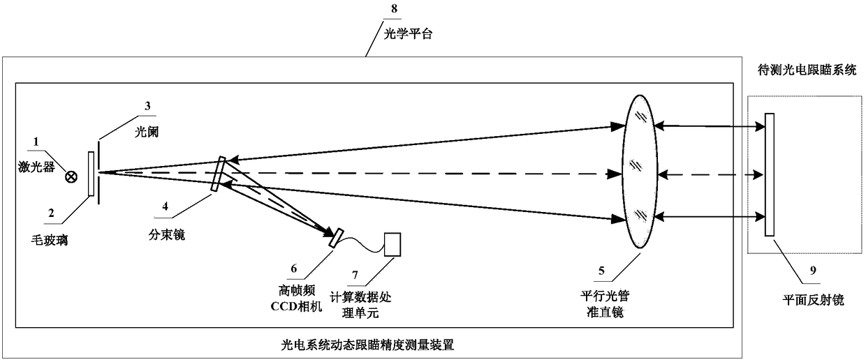
[0020] Such as figure 1 As shown, the debugging object targeted by the preferred embodiment of the present invention is the measuring device for tracking and aiming accuracy of the photoelectric system. The measuring device includes an optical platform 8 and a laser light source 1 installed thereon, a frosted glass 2, an aperture diaphragm 3, a beam splitter 4, a transmissive collimator mirror 5, a high frame rate CCD camera 6, a computer image The acquisition and processing unit 7 is composed. In this embodiment, the size of the optical table 8 is 2.4m×1.2m; the laser light source 1 is a semiconductor fiber coupled continuous laser with a wavelength of 808nm, the spatial distribution of the light spot is Gaussian distribution, and the beam quality M 2 ≤1.1, the beam pointing stability is ≤1μrad, and the power stability is 2%; the ground gla...


PUM


Abstract

The invention provides an adjusting and correcting method of a light path of a photoelectric system tracking-pointing precision measuring device. The measuring device is mainly composed of an opticalplatform, a laser light source, ground glass, a small-hole diaphragm, a beam splitter, a parallel light pipe collimating mirror, a high-frame-frequency CCD camera and the like, wherein the laser lightsource, the ground glass, the small-hole diaphragm, the beam splitter, the parallel light pipe collimating mirror, the high-frame-frequency CCD camera and the like are installed on the optical platform. By the adoption of a plane mirror, an optical autocollimation, a pentaprism and a theodolite, the positions of the laser light source, the small hole diaphragm and the high-frame-frequency CCD camera of the photoelectric system tracking-pointing precision measuring device are adjusted and corrected, the adjusting and correcting method has the advantages of being high in precision, easy to operate, convenient and visual, the problem of adjusting and correcting the light path of the photoelectric system tracking-pointing precision measuring device is solved, and not only is technological guarantee provided for the development of a space laser communication tracking-pointing technology, but also a reference basis is provided for designing a space laser communication system tracking-pointing precision measuring device.

Description

technical field [0001] The invention belongs to the technical field of optical metrology and testing, and mainly relates to an optical path adjustment method of a tracking and aiming accuracy measuring device of a photoelectric system, in particular to an optical path adjusting method of a tracking and aiming accuracy measuring device of a space laser communication system. Background technique [0002] Tracking and aiming accuracy is one of the important index parameters to evaluate the tracking and aiming ability of the optoelectronic system. There are mainly four-quadrant detector method, parallel light tube method, etc. The four-quadrant detector method has high sensitivity. Since the laser spot of the photoelectric system is usually not a uniformly distributed rectangular spot, the output value of the four-quadrant differential amplification and the position of the laser spot are nonlinear, so it is not suitable for high-precision measurement. The collimator method usua...

Claims


Application Information

Patent Timeline
Patent Type & Authority Applications(China)
IPC IPC(8): G01M11/04H04N17/00
CPCG01M11/00H04N17/002
Inventor 吴磊黎高平于东钰赵宝珍桑鹏张魁甲吕春莉
Owner 西安应用光学研究所
Why Eureka
Try Eureka