RFID devices for verification of correctness, reliability, functionality and security

a technology of correctness and reliability, applied in the direction of burglar alarm mechanical actuation, burglar alarm by hand-portable objects removal, instruments, etc., can solve the problems of many current car radios being disabled, and achieve the effect of cost-effective circuit design and non-destructive fabrication

Inactive Publication Date: 2010-05-11
EIGENT TECH
View PDF85 Cites 43 Cited by
  • Summary
  • Abstract
  • Description
  • Claims
  • Application Information

AI Technical Summary

Benefits of technology

[0015]The present invention differs from the prior art in that the present invention provides one or a network of passive or active radio frequency identification (RFID) transceivers and antenna elements in different numbers, in various network sizes, in different configurations and on various substrates. The RFID transceiver can be co-located with standard semiconductor devices or printed circuit boards, for cost-effective circuit design and non-destructive fabrication test and analysis of integrated circuits and printed circuit boards after fabrication, and to locate, track and identify the integrated circuit, printed circuit b

Problems solved by technology

Also, many current car radios are disabled when removed from vehicles (i

Method used


Image

  • RFID devices for verification of correctness, reliability, functionality and security
  • RFID devices for verification of correctness, reliability, functionality and security
  • RFID devices for verification of correctness, reliability, functionality and security

Examples


second embodiment

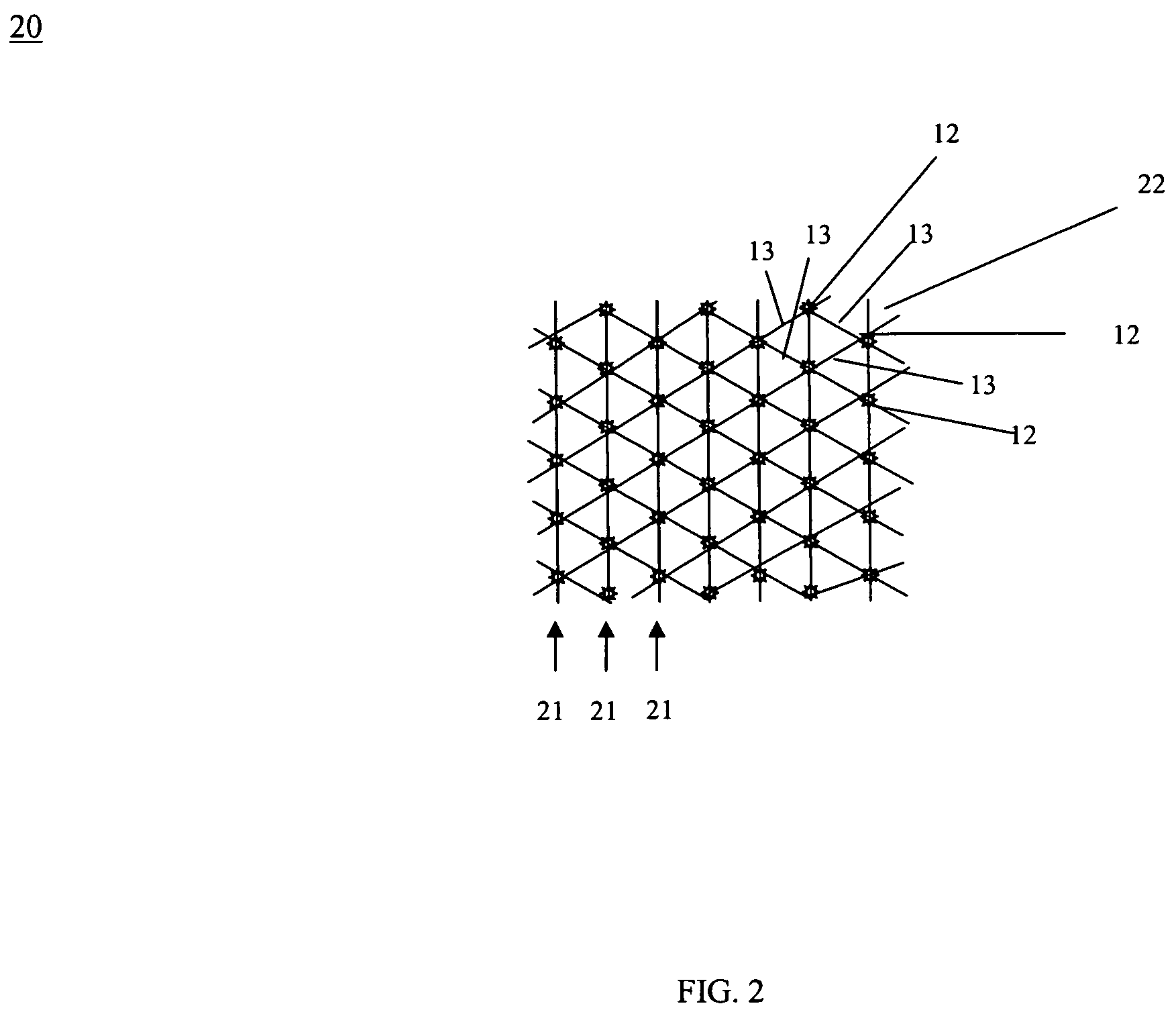
[0041]In a second embodiment, as shown in FIG. 2, RFID device 20 comprises a plurality of RFID transceivers 12 networked to one another with connectors 13 in a connected network comprising a plurality of connected rows 21 of RFID transceivers 12 on mesh bag 22. Adjacent RFID transceivers 12 in the same or adjacent rows 21 are connected to one another in a mesh pattern. Mesh bag 22 can be formed in various sizes. Mesh bag 22 can be formed of, for example, polymer or plastic materials or synthetic fiber or natural fiber materials.

third embodiment

[0042]In a third embodiment, as shown in FIG. 3, RFID device 30 comprises a plurality of RFID transceivers 12 networked to one another with connectors 13 in a connected network comprising a plurality of connected rows 21 of RFID transceivers 12 on sheet 32. Adjacent RFID transceivers 12 in the same or adjacent rows 21 are connected to one another in a mesh pattern. Sheet 32 can be formed in various lengths, widths and sizes. Sheet 32 can be formed of, for example, paper, polymer, plastic, transparent films, synthetic fibers, or natural fiber materials.

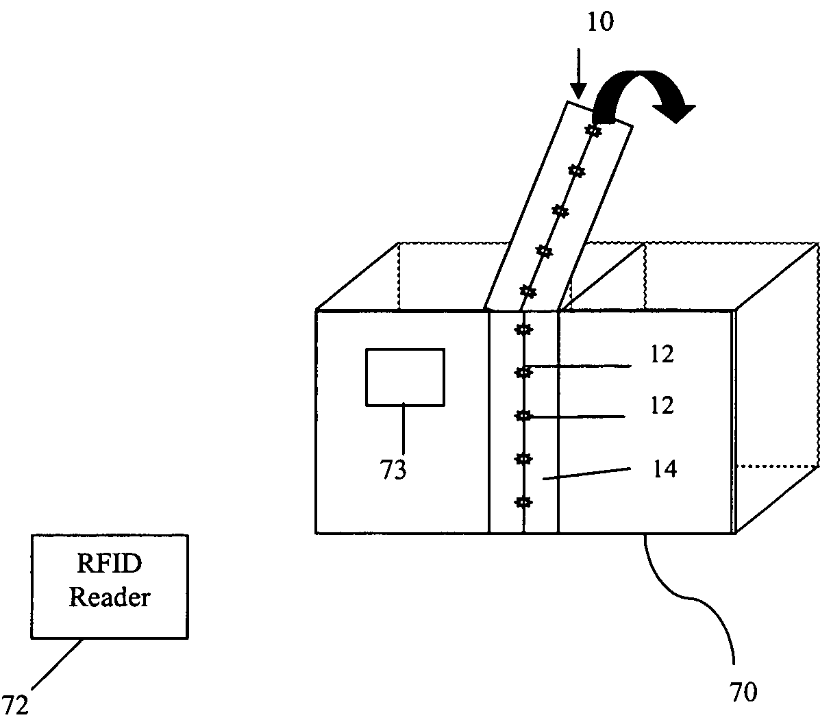
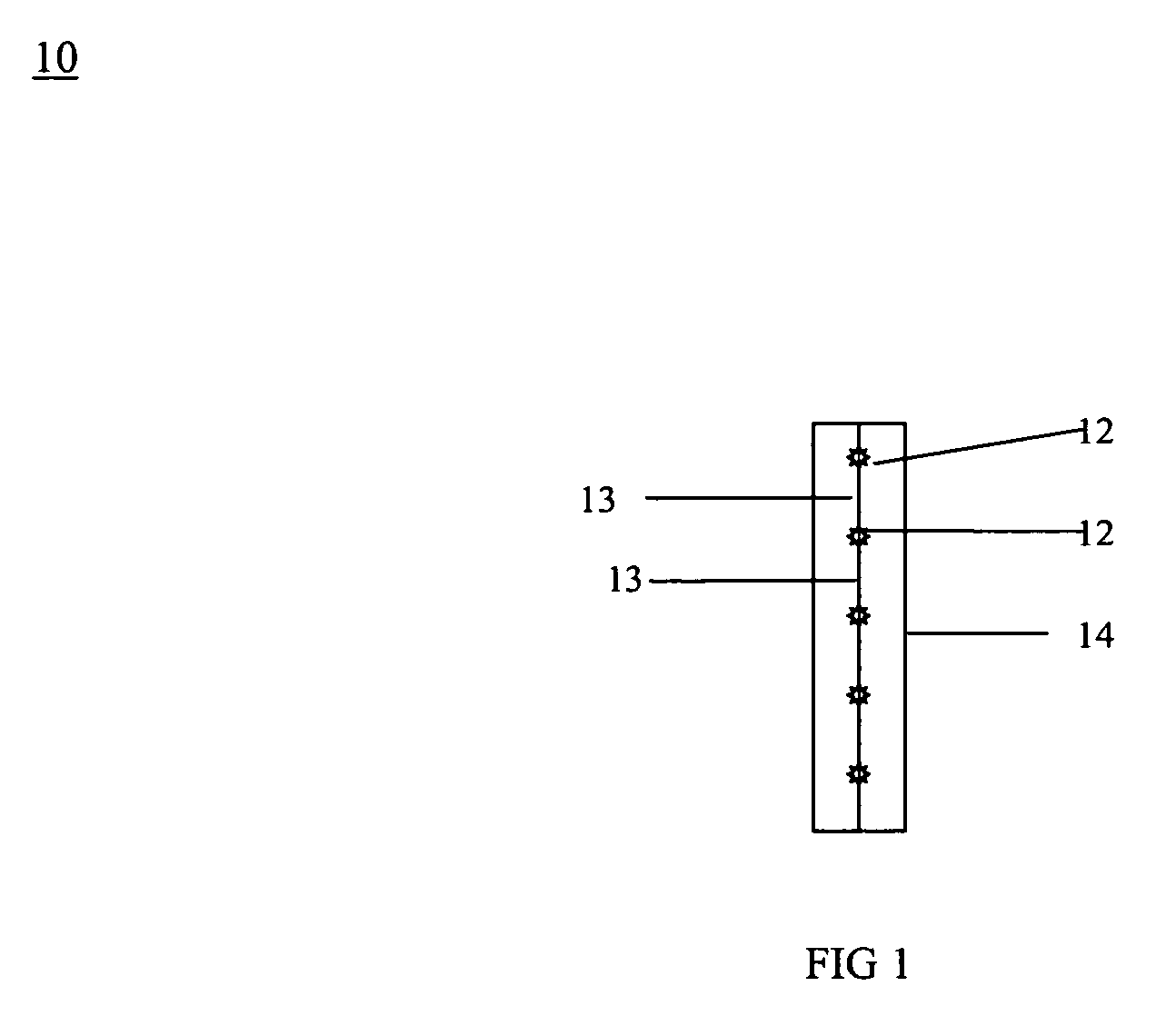
[0043]RFID transceivers 12 when illuminated can respond with either an “end” signal or a “middle” signal depending on whether RFID transceiver 12 is at the end or middle of tape 14 or mesh bag 22 or sheet 32. The state of being of RFID transceivers 12 at the end or middle of tape 14 or mesh bag 22 or sheet 32 can change and will change when tape 14 or mesh bag 22 or sheet 32 is cut or altered.

[0044]RFID transceivers 12 are arranged on ...


PUM


Abstract

The present invention differs from the prior art in that the present invention provides one or a network of passive or active radio frequency identification (RFID) transceivers and antenna elements in different numbers, in various network sizes, in different configurations and on various substrates. The RFID transceiver can be co-located with standard semiconductor devices, for cost-effective circuit design and non-destructive fabrication test and analysis of integrated circuits and printed circuit boards after fabrication, and to locate, track and identify the integrated circuit, printed circuit boards and products in which they are implemented. The RFID transceivers can be coupled to substrates containing matter in gas, liquid, or solid form, such as medical devices like breast implants, for effective monitoring of the substrates to ensure that the substrate is in an unaltered state and the matter is still contained securely within. The RFID transceivers can be coupled to secure tapes of various lengths and widths and mesh bags or sheets of various sizes and they can be applied at the carton-level using them to locate, track and identify the integrated circuit, printed circuit boards and products in which they are implemented and/or the cartons in which they were placed.

Description

CROSS REFERENCE TO RELATED APPLICATION[0001]This application claims the benefit of U.S. Provisional Patent Application No. 60 / 655,010 filed Feb. 22, 2005 and U.S. Provisional Patent Application No. 60 / 676,710 filed May 2, 2005 the entirety of which are both hereby incorporated by reference into this application.BACKGROUND OF THE INVENTION[0002]1. Field of the Invention[0003]The present invention provides RFID device comprising a network of radio frequency identification (RFID) transceivers and antenna elements in different numbers, in various network sizes, in different configurations and on various substrates, a method for making the same and a method of using the RFID devices.[0004]2. Description of Related Art[0005]A radio-frequency identification (RFID) transceiver is a device that includes RF (radio frequency) circuits, control logic and memory, plus an antenna, all mounted on a supporting substrate. It receives an electronic signal, generates a response signal, and then transm...

Claims


Application Information

Patent Timeline
IPC IPC(8): G06K19/06G06K19/00G08B13/14H04Q5/22
CPCG06K19/07749G08B13/2417G06K19/07798H04Q2213/13095G06K19/072
Inventor WARNER, ROBERTWINTERS, JACKMCNAIR, BRUCE
Owner EIGENT TECH
Why Eureka
Try Eureka