System and method for controlling multiple DC fans

a technology of dc motors and control circuits, applied in the direction of motor/generator/converter stoppers, multiple dynamo-motor starters, dynamo-electric converter control, etc., can solve the problems of limiting the maximum power, bulky drive circuitry of variable speed fan motors, and limiting the power of dc motors

Inactive Publication Date: 2010-05-11
MINEBEAMITSUMI INC
View PDF14 Cites 19 Cited by
  • Summary
  • Abstract
  • Description
  • Claims
  • Application Information

AI Technical Summary

Problems solved by technology

Drive circuitry for variable speed fan motors, however, is typically bulky and itself generates heat that has to be removed from the frame by the airflow.
This in turn limits the maximum power rating of the drive circuit transistors that can be used, thus limiting the power of the DC motor resulting in low efficiency airflow.
In the prior art there are, therefore, limiting factors in the performance of the fan due to the volume occupied by the drive circuitry.
Another consideration when the drive circuitry is mounted on the motor hub is the cost of replacing a failed motor.
As is known in the art, the motor may fail due to overheating of the windings or a mechanical breakdown, e.g., a damaged ball bearing assembly retaining the spindle of the motor.
Typically, the most expensive part of the fan is a microcontroller integrated circuit in the drive circuit and not the DC motor itself.
Therefore, also taking the other electronic components in the drive circuit into consideration, it is much more costly to replace the motor hub assembly than it is to replace only the DC motor component.
There is no coordinated control of the set of fans in order to stabilize the airflow through the frame.

Method used


Image

  • System and method for controlling multiple DC fans
  • System and method for controlling multiple DC fans
  • System and method for controlling multiple DC fans

Examples


Embodiment Construction

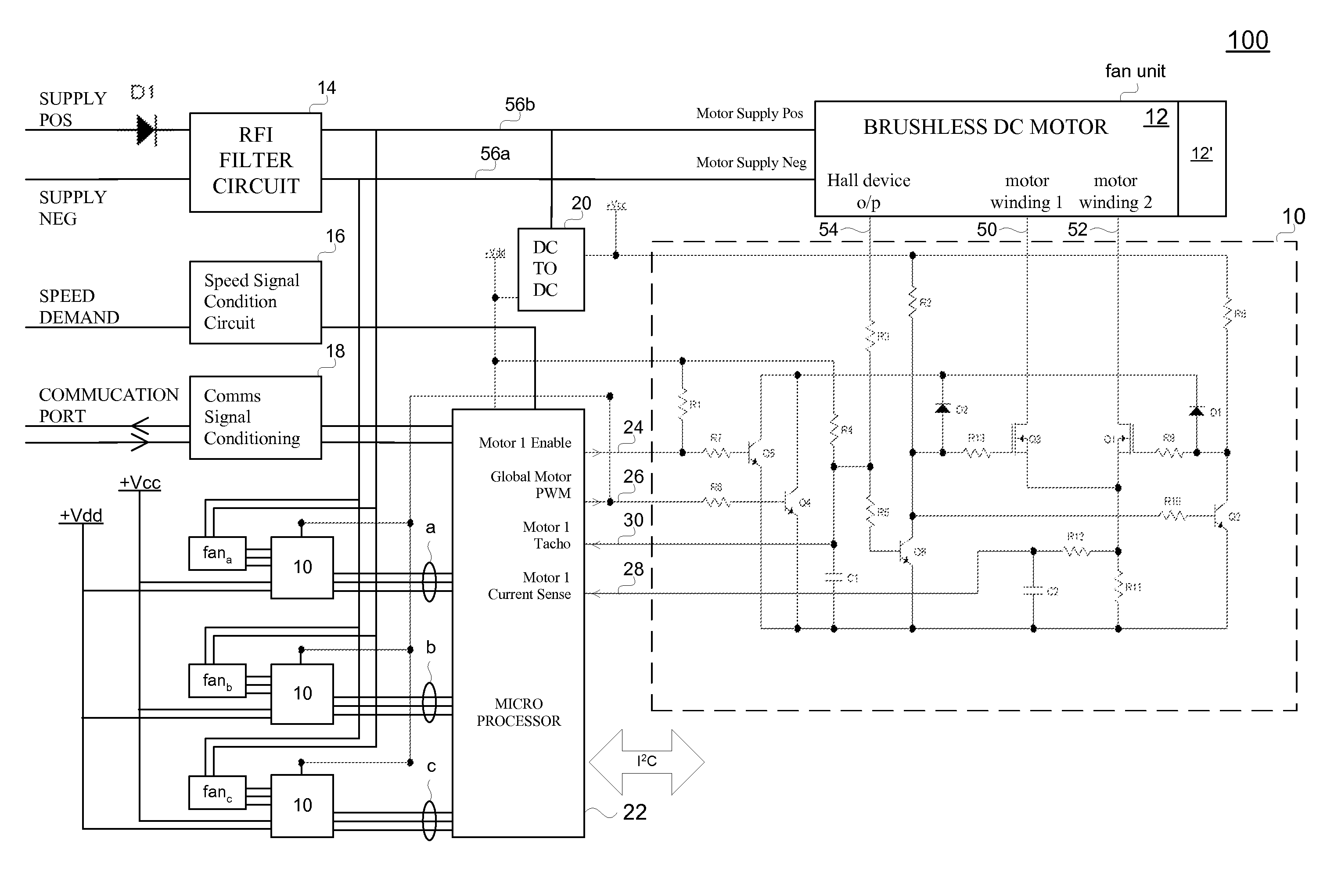
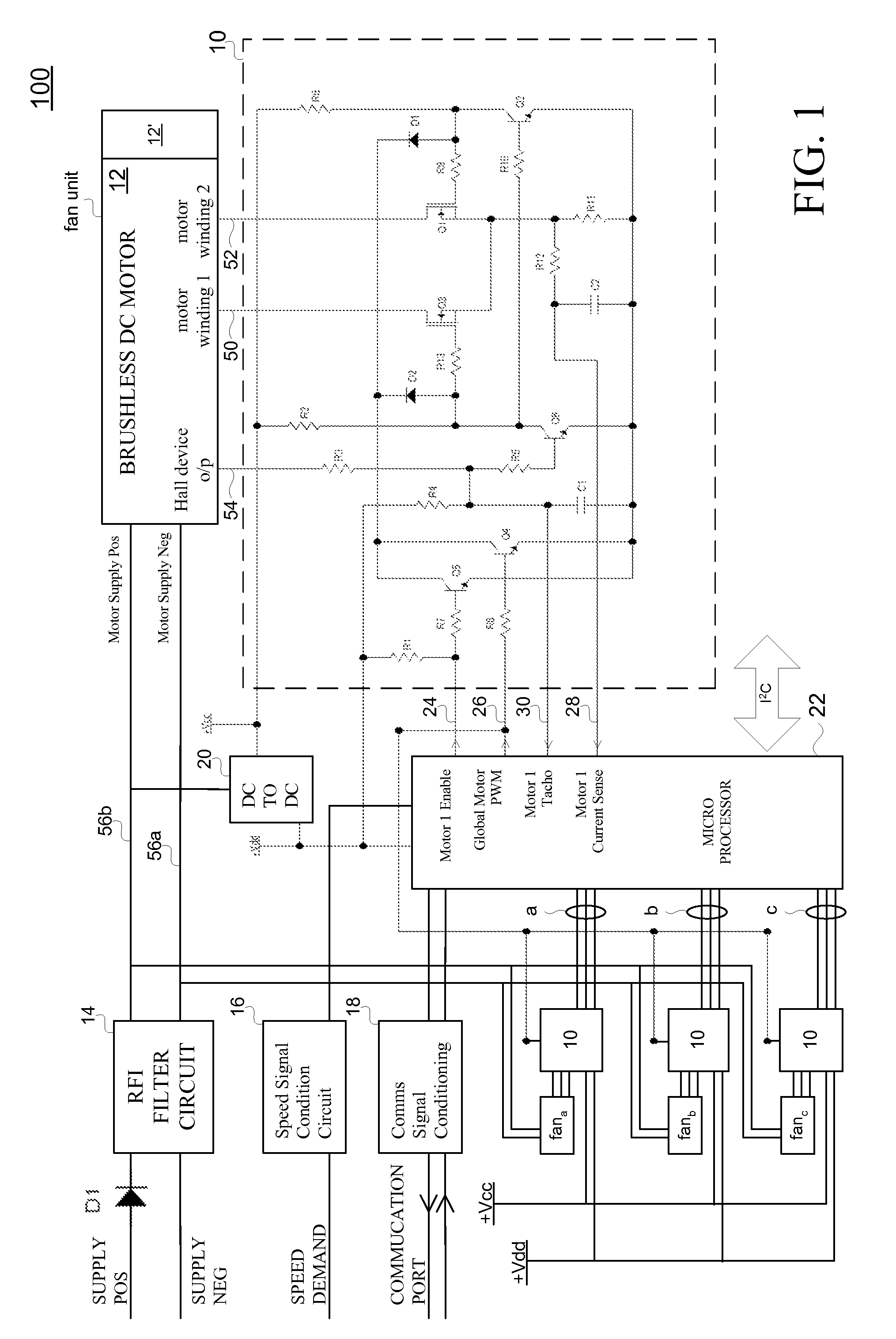
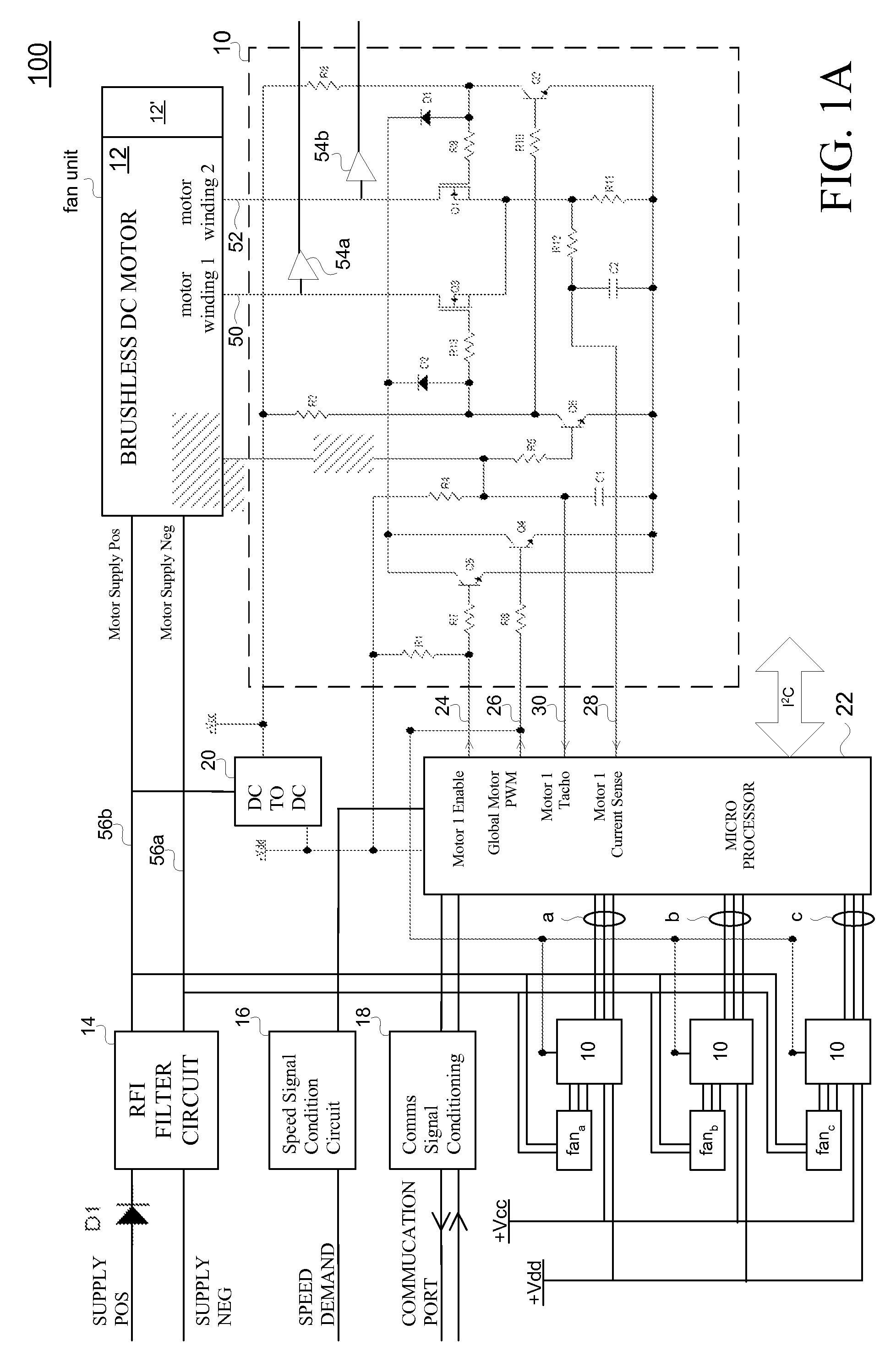
[0022]The present invention has particular relevance in fans that are used to cool contemporary rack-mounted electronic equipment where its electronics are tightly packaged. For example, 1 U equipment packages its electronics within a 1.75 inch tall space. Fans for cooling such equipment are thus on the order of 1.75 inches tall. Conventional fans used in such applications incorporate the fan drive electronics within the small volume of the fan hub.

[0023]Since fans (more specifically their respective motors) are driven by electric current and high speed fan operation (which is desired for greater cooling) have high power requirements, the analog electronic components of the fan drive electronics are necessarily physically large devices in order to handle these high current flows. Such components impose a constraint on how small (e.g., diameter) the fan hub, to which the electronics are mounted, can be. This in turn imposes a limit on the area of air flow that the fan can provide. In...


PUM


Abstract

A system and method for controlling multiple cooling fans is presented. The circuitry for directly driving each of the motors is removed from the motor casings, thus increasing air flow and reducing replacement costs should a motor fail. The system includes a common processor for centrally controlling the speeds of the motors and monitoring the performance of each of the multiple motors.

Description

BACKGROUND OF THE INVENTION[0001]The present invention relates to the control of DC motors. In particular, the present invention relates to a system and method for controlling multiple DC motors driving cooling fans.[0002]Much electronic equipment is cooled by fans to remove heat generated by the operation of the equipment. Typically, the fans are incorporated into the chassis (referred to as a fan bank, fan panel, etc.), frame, or cabinet housing the equipment and force air through the cabinet to cool the components contained therein. For equipment that generates a lot of heat, multiple fans are used, and may be switched on or off in response to temperatures inside the frame. It is not uncommon to find a bank of six to eight fans cooling a frame. Each fan may be independently controlled by an associated temperature sensor, or a single temperature sensor may control all fans in the bank simultaneously.[0003]Another arrangement of fan control is to vary the speed of the fans in respo...

Claims


Application Information

Patent Timeline
Patent Type & Authority Patents(United States)
IPC IPC(8): H02P7/08H02P5/00
CPCH02P5/68
Inventor FRANKEL, SCOTTSTRIKE, NIGELHARDT, ERICSHINANO, TAKASHI
Owner MINEBEAMITSUMI INC
Why Eureka
Try Eureka