System and method for improved engraving of gravure cylinders by adjusting engraving signal responsive to movement of shoe position

a technology of engraving signal and gravure cylinder, which is applied in the field of engraving devices, can solve the problems of inaccurate size and/or shape of engraved cells, and achieve the effect of reducing mass

Inactive Publication Date: 2010-05-11
OHIO GRAVURE TECH
View PDF7 Cites 1 Cited by
  • Summary
  • Abstract
  • Description
  • Claims
  • Application Information

AI Technical Summary

Benefits of technology

[0010]In one aspect, one embodiment provides a system and method for reducing the mass that is following the surface of the cylinder and, therefore, the engraved response to cylinder surface irregularities.
[0014]Another object of one embodiment is to able customers to use substantially lower quality cylinders, that is, surface cylinders with substantially greater surface irregularities and to improve printing, even though it is done from lower quality cylinders.
[0015]Still another advantage is that it may be possible to use lower shoe pressures, which reduces the marking of the engraved surface and coupling less energy into vibration modes in the engraving head and carriage on which the engraving head is mounted.
[0016]Another embodiment is that the moving shoe technology is rather simple in design and robust and should enable easier manufacturability with lower precision tooling.

Problems solved by technology

All of this causes the size and / or shape of the engraved cells to be inaccurate.

Method used


Image

  • System and method for improved engraving of gravure cylinders by adjusting engraving signal responsive to movement of shoe position
  • System and method for improved engraving of gravure cylinders by adjusting engraving signal responsive to movement of shoe position
  • System and method for improved engraving of gravure cylinders by adjusting engraving signal responsive to movement of shoe position

Examples


Embodiment Construction

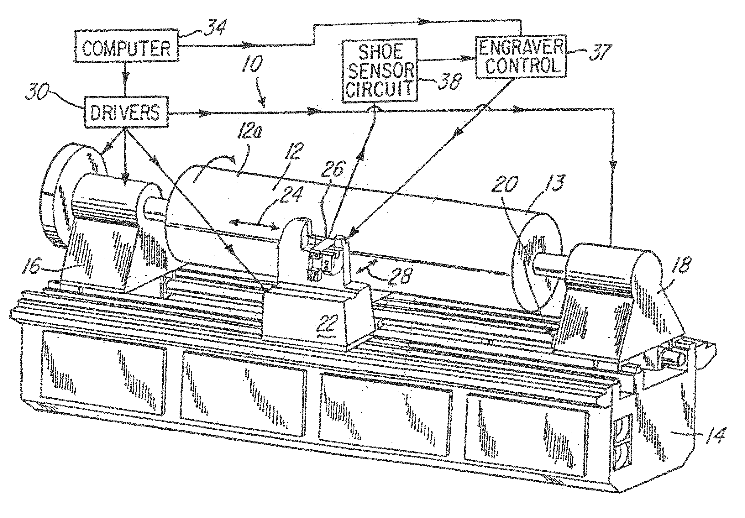
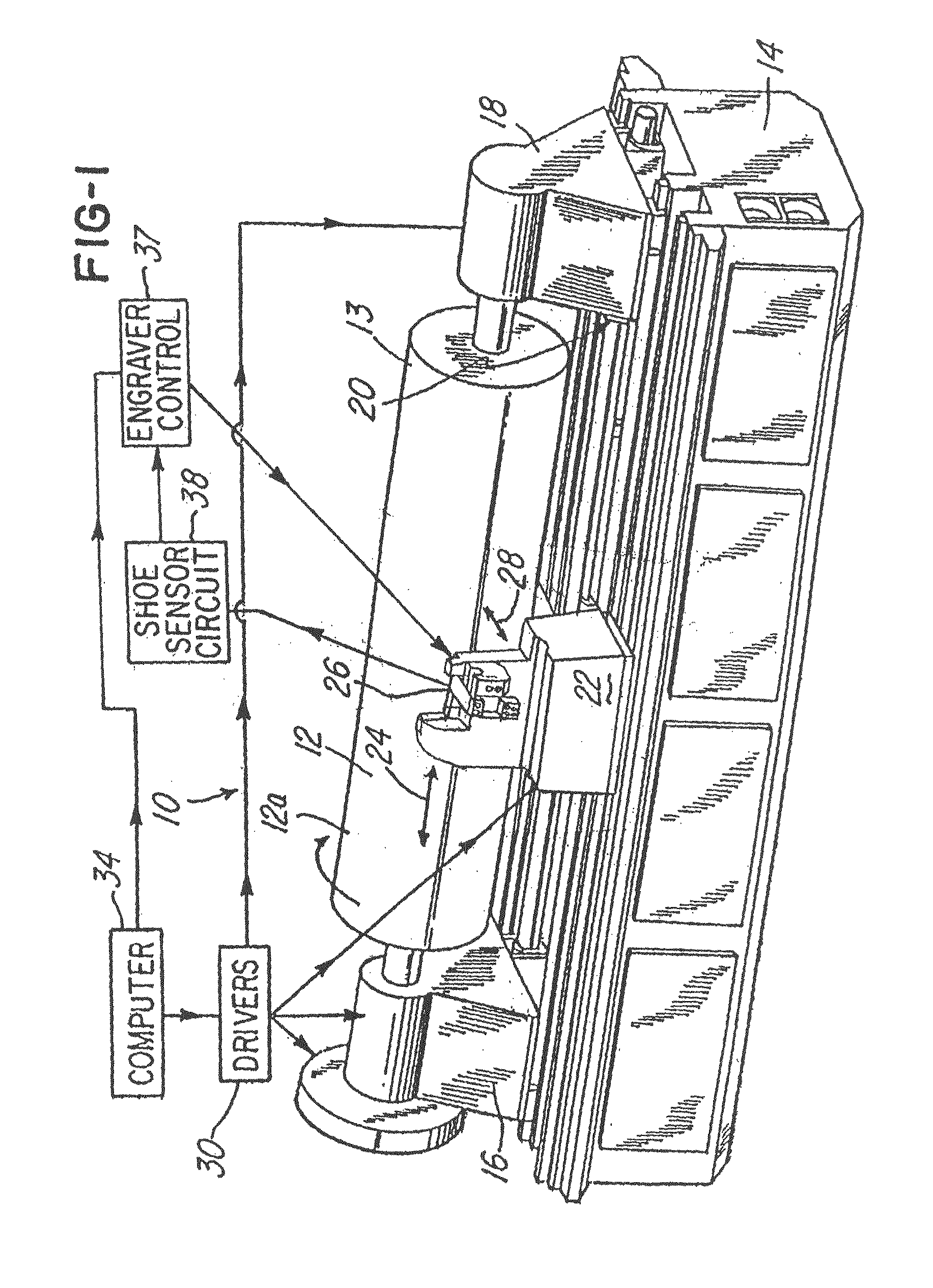
[0030]FIG. 1 is a general perspective view of a preferred embodiment of an engraver, designated generally as engraver 10.

[0031]In the embodiment being described, the engraver 10 is a gravure engraver, but the invention may be suitable for use in other types of engravers, such as laser engravers.

[0032]The engraver 10 is a gravure engraver for engraving a surface 12a of a cylinder 12 which will subsequently be used to print a predetermined pattern of cells on a substrate. The cylinder 12 will then be placed in a printing machine and in a gravure printing process to thereby print via the gravure printing process on the substrate. The cylinder 12 has the surface 12a which has an engravable coating, such as copper.

[0033]The engraver 10 comprises a base 14 having a headstock 16 and a tailstock 18 slidably mounted on a bed 20 situated on the base 14. The headstock 16 and tailstock 18 are slidably and adjustably mounted on the bed 20 with suitable bearings and drive train (not shown) such t...


PUM


Abstract

An engraver having a shoe sensor system for sensing a movement of the shoe and for adjusting an engraving signal in response thereto.

Description

BACKGROUND OF THE INVENTION[0001]1. Field of the Invention[0002]This invention relates to engraving devices, and more particularly to a method and apparatus for detecting surface irregularities and for correct adjustment of engraving in response thereto.[0003]2. Description of the Related Art[0004]Prior art devices of the type shown in U.S. Pat. Nos. 4,450,486; 5,424,846; 5,438,422; 5,424,845; 5,329,215; 5,652,659 typically comprise an engraving head having an engraving device, such as a diamond stylus, and a guide shoe. The guide shoe bore against a surface of a cylinder and provided a reference for the engraving process. An electromagnetic driver mounted within the engraving head caused the engraving device to oscillate into engraving contact with the cylinder as the cylinder rotated about its cylindrical axis, thereby causing either a helical or cylindrical tract of engraved areas or cells to be engraved on the surface of the cylinder.[0005]The cylinders engraved oftentimes had s...

Claims


Application Information

Patent Timeline
Patent Type & Authority Patents(United States)
IPC IPC(8): B41C1/04
CPCB41C1/045
Inventor FRASER, JOHN WILLIAMWINTER, CHRISTOPHER DARRELL
Owner OHIO GRAVURE TECH
Why Eureka
Try Eureka