
Audio bandwidth expansion

a technology of audio frequency and expansion, applied in the field of digital signal processing, can solve the problems of time domain aliasing, perceptual distortion, and limited and achieve the effect of increasing the bandwidth of the audio frequency

Active Publication Date: 2010-05-11
TEXAS INSTR INC
View PDF9 Cites 20 Cited by
  • Summary
  • Abstract
  • Description
  • Claims
  • Application Information

AI Technical Summary

Benefits of technology

This approach provides natural sound quality with adaptive bandwidth expansion, reducing aliasing and enhancing low frequencies effectively, while maintaining computational efficiency and avoiding phase distortion.

Problems solved by technology

This is because their bandwidths have been limited due to the channel / media capacity of transfer / storage systems.
The problem with this method is that, time domain aliasing is caused due to the plain frequency domain weighting.
This can lead to perceptual distortion.
However, these methods are incapable of complete suppression of aliasing.
This method is very simple, but a small threshold will be susceptible to noise and a large threshold will fail for small input signals.
Another problem is that, even if there is no real cut-off in the input spectrum, the simple method would identify an inappropriate frequency as the cut-off frequency.
Then, BWE algorithms will generate unwanted high frequencies, which could result in audible distortion, over the already existing high frequency components of the input signal.
Another bandwidth problem occurs at low frequencies: bass loudspeakers installed in electric appliances such as flat panel TV, mini-component, multimedia PC, portable media player, cell-phone, and so on cannot reproduce bass frequencies efficiently due to their limited dimensions relative to low frequency wavelengths.
Although equalization can help reproduce the original bass sound, the amplifier gain for the bass frequencies may be excessively high.
As a result, it could overdrive the loudspeaker, which may cause non-linear distortion.
Also, the dynamic range of the equalized signal would become too wide for digital representation with finite word length.
The overuse of the effect for a wide range of frequencies leads to unnatural or unpleasant sound.
Then, the amount of harmonics will be zero or insufficient for small input signal, and too much for large input signal.

Method used


Image

  • Audio bandwidth expansion
  • Audio bandwidth expansion
  • Audio bandwidth expansion

Examples


example values

are

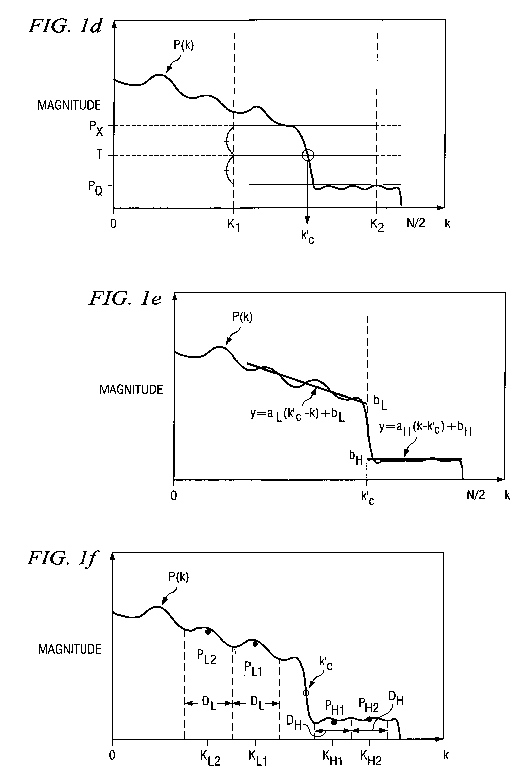
KH1=kc′+N / 16, KH2=kc′+N / 8

With these values aH and bH can be computed by just switching L to H in the foregoing.

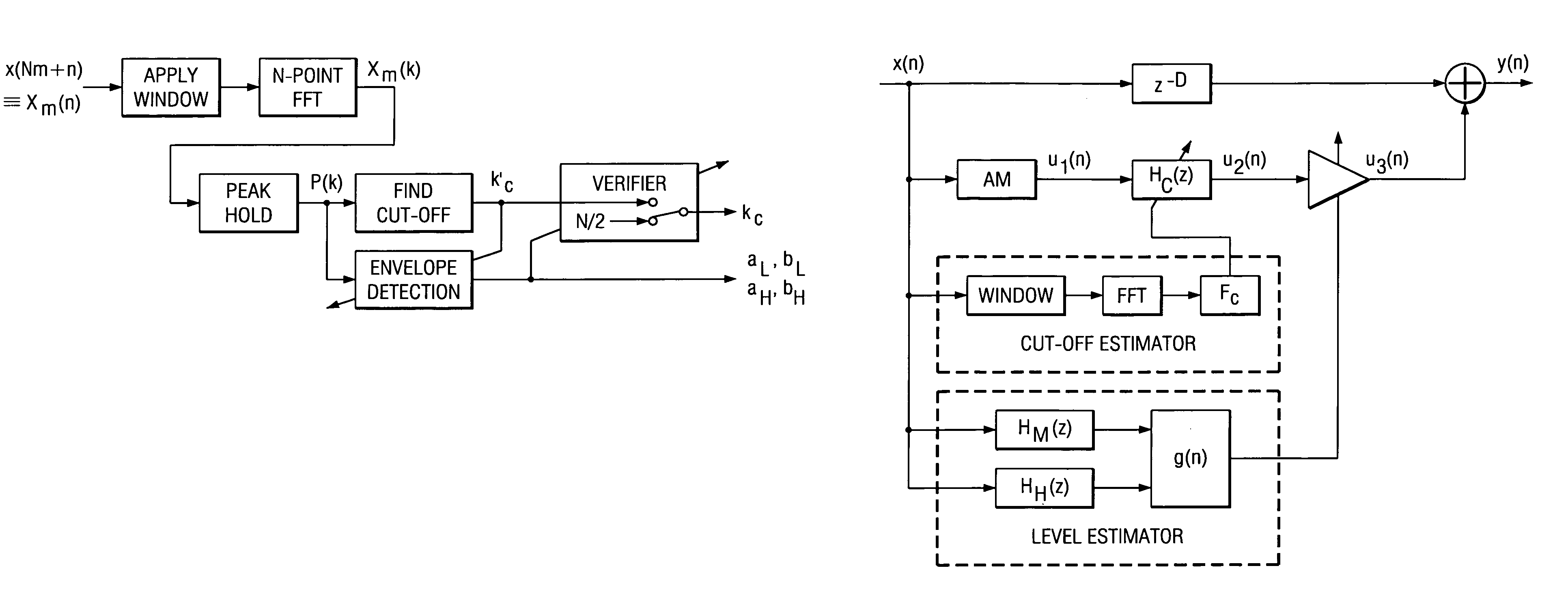
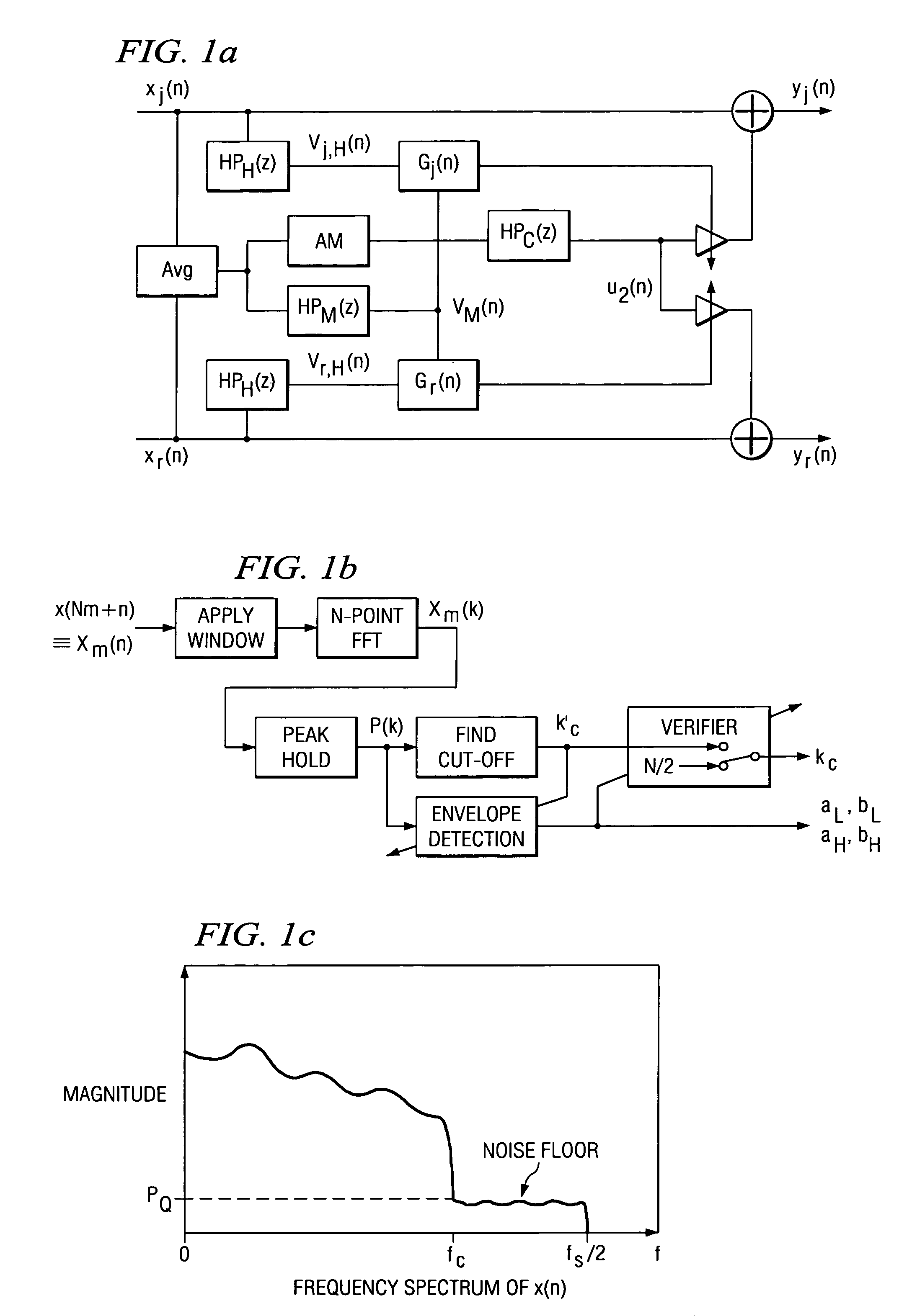
[0037]In the preferred embodiment method, the candidate cut-off frequency kc′ is verified as

[0038]kc=kc′if⁢⁢(bL-bH)>b=N / 2otherwise

where kc is the final estimation of the cut-off frequency, and b is a threshold. The condition indicates that there should be a drop-off larger than b (dB) at kc′ so that the candidate can be considered as the true cut-off frequency.

[0039]There are many other possible ways to verify the candidate cut-off frequency kc′ using aL, bL, aH and bH. Another simple example is

bL>>bH

This condition means that the offsets should be on the expected side of the threshold. Even more sophisticated and robust criteria may be considered using the slopes aL and aH.

5. BWE in Time Domain

[0040]FIG. 1g shows the block diagram of a preferred embodiment time domain BWE implementation. The system is similar to the preferred embodiment of sections 2 and 3 but w...


PUM


Abstract

Bandwidth expansion for audio signals by frequency band translations plus adaptive gains to create higher frequencies; use of a common channel for both stereo channels limits computational complexity. Adaptive cut-off frequency determination by power spectrum curve analysis, and bass expansion by both fundamental frequency illusion and equalization.

Description

CROSS-REFERENCE TO RELATED APPLICATIONS[0001]This application claims priority from provisional applications Nos. 60 / 657,234, filed Feb. 28, 2005, 60 / 749,994, filed Dec. 13, 2005, and 60 / 756,099, filed Jan. 4, 2006. Co-assigned, patent application No. 60 / 660,372, filed Mar. 9, 2005 discloses related subject matter.BACKGROUND OF THE INVENTION[0002]The present invention relates to digital signal processing, and more particularly to audio frequency bandwidth expansion.[0003]Audio signals sometimes suffer from inferior sound quality. This is because their bandwidths have been limited due to the channel / media capacity of transfer / storage systems. For example, cut-off frequencies are set at about 20 kHz for CD, 16 kHz for MP3, 15 kHz for FM radio, and even lower for other audio systems whose data rate capability are poorer. At playback time, it is beneficial to recover high frequency components that have been discarded in such systems. This processing is equivalent to expanding an audio si...

Claims


Application Information

Patent Timeline
Patent Type & Authority Patents(United States)
IPC IPC(8): H03G5/00H03G7/00
CPCH04S1/002G10L21/038
Inventor YONEMOTO, AKIHIROTSUTSUI, RYO
Owner TEXAS INSTR INC
Learn More