Guide wire

a technology of guide wires and wires, which is applied in the field of guide wires, can solve the problems of difficult devices such as endovascular stent graft devices, not easily traversing the vasculature, and not being able to control or influence the typical guide wires

Active Publication Date: 2010-05-11
WILLIAM A COOK AUSTRALIA +1
View PDF37 Cites 41 Cited by
  • Summary
  • Abstract
  • Description
  • Claims
  • Application Information

AI Technical Summary

Benefits of technology

[0035]The fourth design feature of the preferred embodiment is an extremely stiff shaft or body portion that provides the strength to guide the interventional device.
[0036]The fifth design feature of the preferred embodiment is a transition from full stiffness to semi-stiff at the proximal end. The semi-stiff proximal portion provides the flexibility needed to allow the interventional delivery system to be loaded onto the wire and advanced without damaging the guide wire lumen or becoming jammed in the interior of the device.

Problems solved by technology

Large, stiff devices such as endovascular stent graft devices, are not controlled or influenced by typical guide wires when they are placed percutaneously.
Very stiff guide wires are typically used with these types of devices; however, the stiff wires tend to be much stiffer than the vessels and will not traverse the vasculature easily.
In addition, it frequently traumatizes the vessel walls.
In addition, the proximal ends of very stiff wires can damage or become lodged in the walls of the guide wire lumen of a delivery system.
These guide wires do not have the characteristics to solve the problems of percutaneous deployment of large stiff devices.
Again these guide wires do not have the characteristics to solve the problems of percutaneous deployment of large stiff devices.
The guide wire described in U.S. Pat. No. 6,254,550, to McNamara, et. al, does not possess the needed stiffness transitions nor the correct shape.
In addition, this patent does not teach the use of a stiffness transition on the proximal end to protect the devices being used with the guide wire.

Method used


Image

  • Guide wire
  • Guide wire
  • Guide wire

Examples


Embodiment Construction

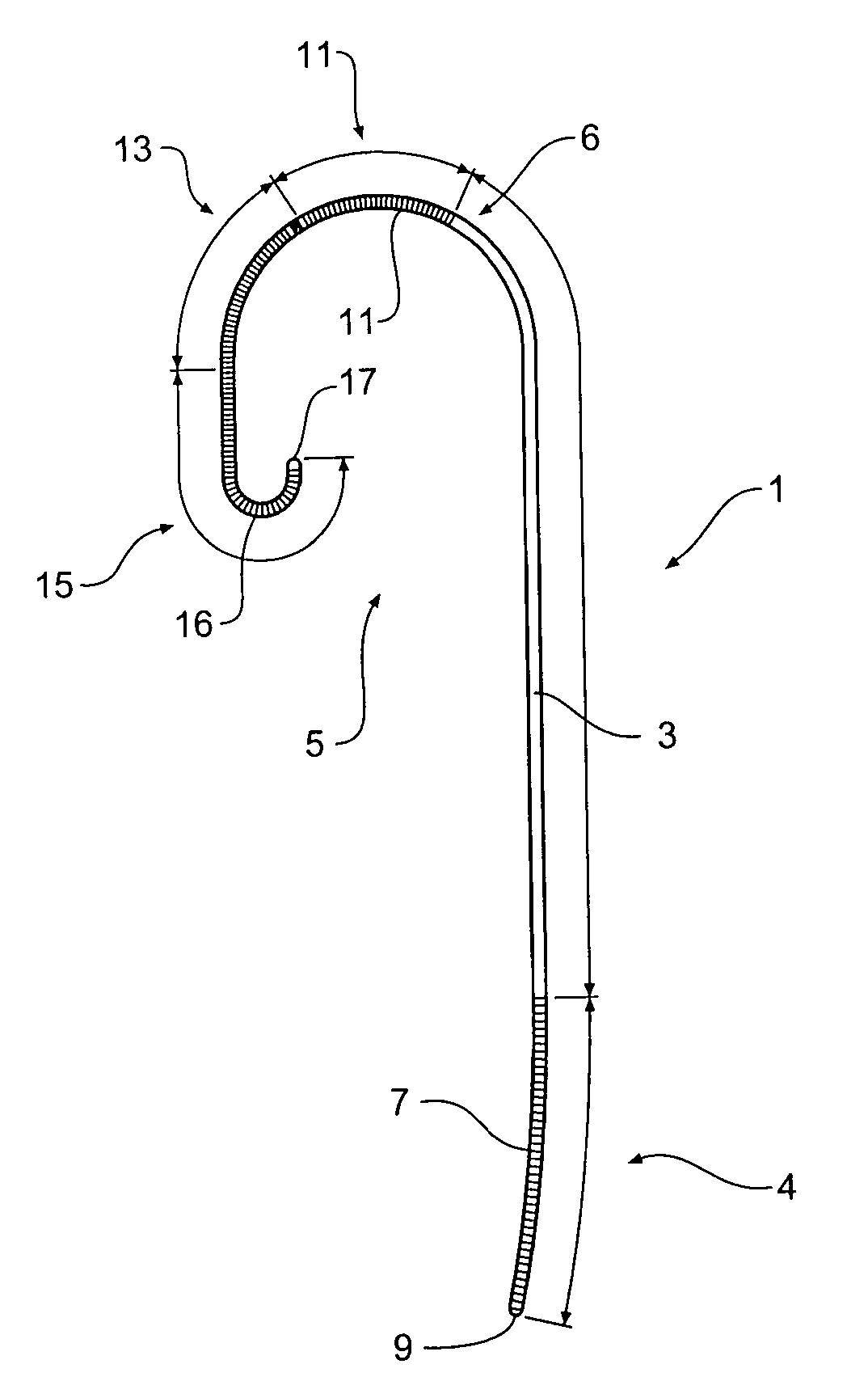
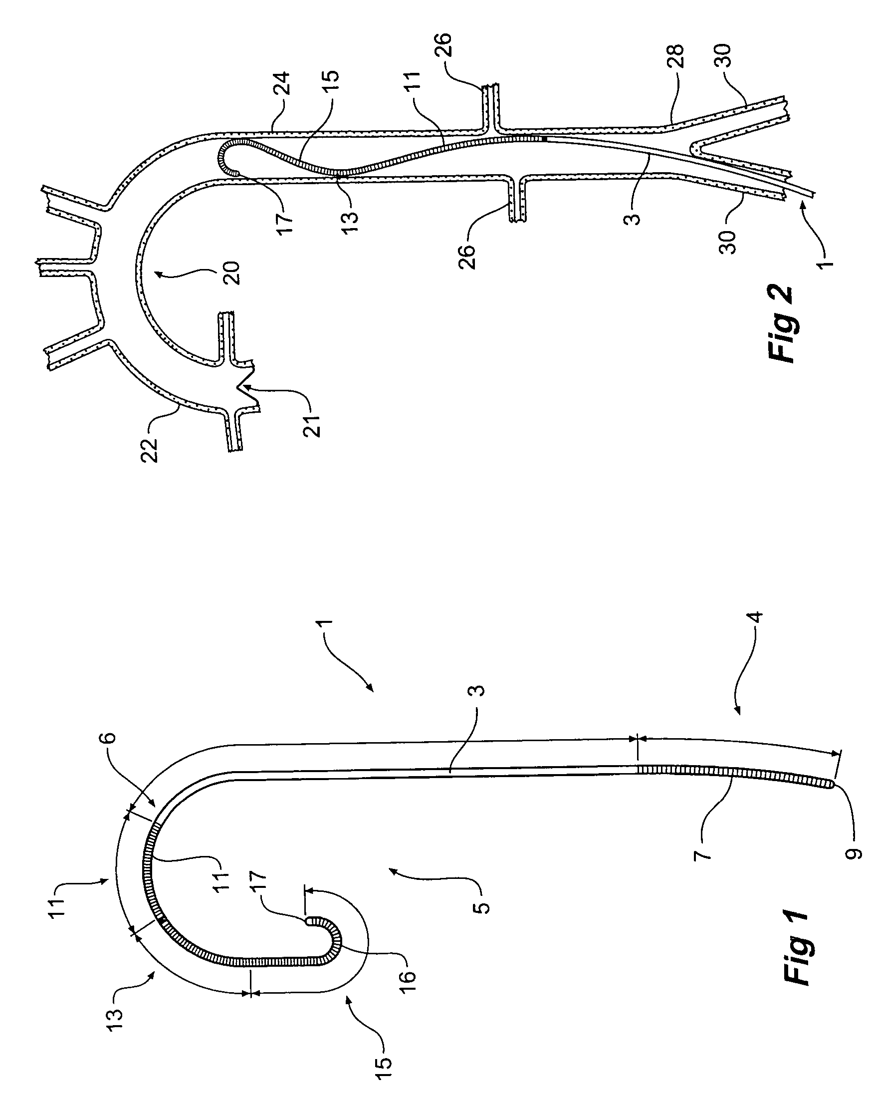
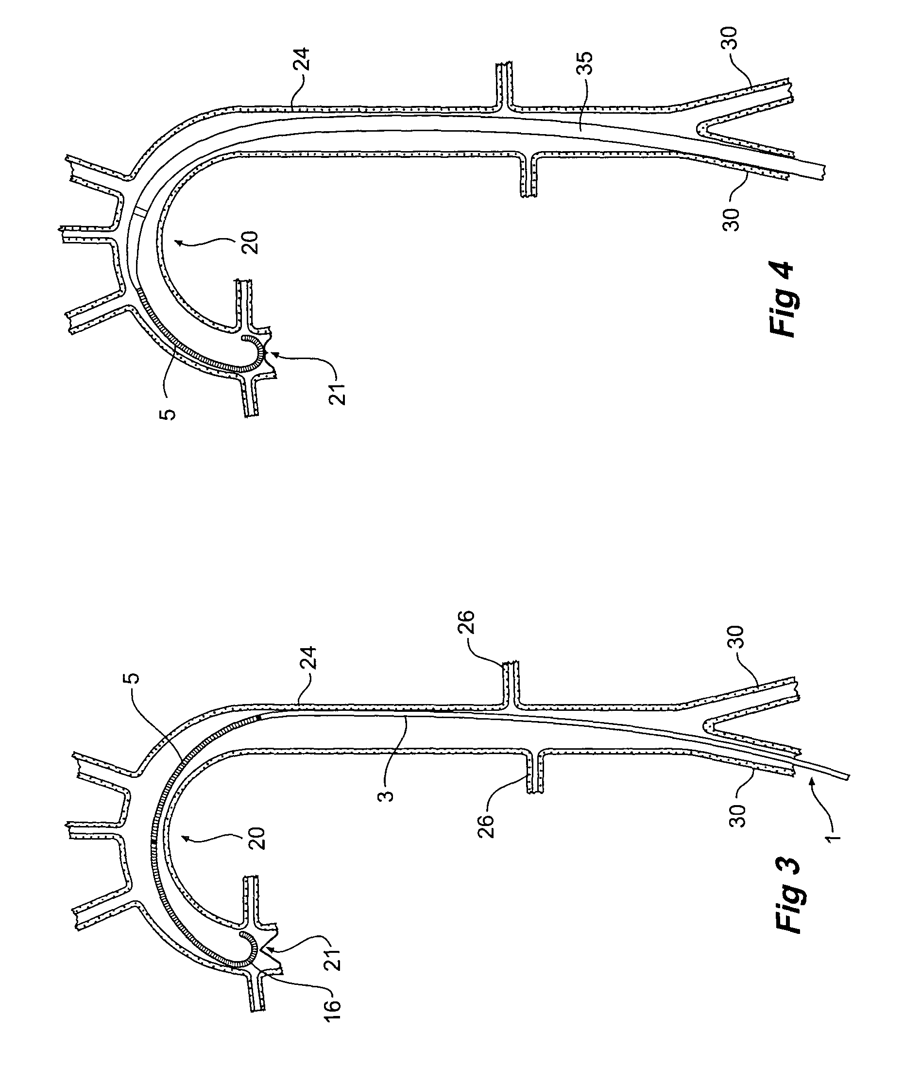
[0053]Now looking more closely at the drawings it will be seen that FIG. 1 shows the general layout of a guide wire according to one embodiment of the invention. The guide wire includes a combination of flexibilities, lengths of the flexible sections and the size and shape of the curves that together result in a guide wire that can be percutaneously introduced through a needle, advanced through the artery without damaging the artery, seat firmly in the anatomy when in place and not “poke” or irritate the aortic heart valve.

[0054]In FIG. 1, the guide wire generally shown as 1 includes a central zone 3, a proximal zone 4 and a distal zone generally shown as 5. The central zone 3 is of substantial stiffness to assist with the deployment of a stent graft deployment device. The proximal zone 4 ranges in stiffness from full stiffness adjacent to the central zone 3 down to a semi-stiff proximal end 9.

[0055]The distal zone 5 includes a first semi-stiff zone 11 which is a transition from ful...


PUM


Abstract

A guide wire (1) to assist percutaneous endovascular deployment which has zones of varying stiffness. An elongate central zone (3) of high stiffness, a proximal zone (4) of transition from high stiffness to semi-stiffness and a distal zone (5) of transition from high stiffness to being relatively flexible. The distal zone (5) has three zones, a semi stiff zone (11) adjacent the central zone, a transition zone (13) being of flexibility of from semi-stiff extending to flexible and a tip zone (15) being of high flexibility. The distal tip has a small J curve (16) to ensure that it is atraumatic in vessels and to prevent damage to the aortic heart valve. The distal zone (5) can also have a large curve to assist with anchoring the guide wire into the aortic arch.

Description

CROSS-REFERENCE TO RELATED APPLICATIONS[0001]This application claims priority of provisional application Ser. No. 60 / 405,161, filed Aug. 22, 2002.TECHNICAL FIELD[0002]This invention relates to a guide wire for deploying an endovascular deployment device and particularly for deploying a stent graft into the thoracic arch region of the aorta.BACKGROUND OF THE INVENTION[0003]Use of the percutaneous entry technique for medical procedures has expanded rapidly over the last few years. Originally, percutaneous entry was used for the introduction of small, flexible catheters for diagnostic radiographic studies. The use of percutaneous entry rapidly expanded to therapeutic devices such as balloon angioplasty devices, occlusion devices and now to endovascular stent graft delivery.[0004]In the percutaneous entry technique, guide wires are used to guide the catheter through a needle puncture site, into the vessel and up to a target anatomy. Guide wires, in general, are simple devices that will ...

Claims


Application Information

Patent Timeline
Patent Type & Authority Patents(United States)
IPC IPC(8): A61M25/00
CPCA61M25/09A61M25/09033A61M25/0041A61M2025/09175A61M2025/09133A61M2025/0915A61M2025/09083
Inventor HARTLEY, DAVID ERNESTCHRISTIANSEN, FRANK KARHU
Owner WILLIAM A COOK AUSTRALIA
Why Eureka
Try Eureka