Isokinetic sampling

a sampling method and isokinetic technology, applied in the field of isokinetic sampling, can solve the problems of low flow rate, poor measurement of gor and non-representative pvt samples, and inability to cope with high flow rate, etc., and achieve the effect of accurate measurement of flow ra

Inactive Publication Date: 2010-05-18
SCHLUMBERGER TECH CORP
View PDF44 Cites 39 Cited by
  • Summary
  • Abstract
  • Description
  • Claims
  • Application Information

AI Technical Summary

Benefits of technology

[0043]Preferably the method further includes the step of separating said sampled portion into a sampled liquid flow and a sampled gas flow, and said step of measuring the sampled flow rate includes measuring the flow rate of the sampled liquid flow and the flow rate of the sampled gas flow. Either or both of these sampling flows may be measured using a Coriolis flow meter. This allows more accurate measurement of the flow rates of the different phases of the fluid stream. A Coriolis flow meter also allows the density of the flow to be measured.
[0044]In certain embodiments the step of measuring the total flow rate includes measuring the density of the fluid stream. The step of measuring the total flow rate may include measuring a differential pressure, which may, for example, be measured using a Venturi meter, or be an impact pressure measured using a Pitot tube.
[0045]Preferably the step of measuring the total flow rate is carried out continuously or repeatedly during the sampling process.
[0046]Preferably the step of controlling the flow rate of the sampled portion is carried out continuously or repeatedly during the sampling process.
[0047]The continuous or repetitive measuring of the total flow rate and controlling of the flow rate of the sampled portion allows correction of the flow rate of sampled portion in response to changes in the mass flow rate of the main flow stream.
[0048]In this respect, the term “continuous” also includes repeated discrete applications of the measuring and controlling steps above at regular intervals, these intervals being shorter than the time scale over which significant changes in the total mass flow rate of the main stream occur.

Problems solved by technology

Furthermore, PVT data often have a significant impact on processing facility designs and specifications, and therefore on the profitability of gas-oil field.
Common analysis sampling procedures suffer from deficiencies in either or both of their accuracy and their ability to cope with high flow rates.
For example, a high-rate gas condensate well producing 5-100 MMscf (Millions standard cubic feet) / day with a gas-oil ratio of 3 k-100 k scf / bbl (CGR from 0 to 200 bbl / MMscf) (bbl=barrel of liquid; 1 m3=6.29 bbl), can often overwhelm a test-separator, causing liquid carry-over in the separator gas outlet line, thereby providing poor measurement of the GOR and non-representative PVT samples (if the carry-over is not measured and corrected for).
This normally also results in poor recombination ratios.
Gas condensate wells are particularly problematic for sampling as large volumes of gas are associated with only small volumes of liquid, and the phase behavior will be highly sensitive to the quantity and composition of the liquid phase.
This approach has at least the following disadvantages:1) A test separator is needed for wellhead sampling operations, which is bulky and expensive (FIG. 1).2) The test separator can be overwhelmed by high-rate gas wells, leading to liquid carry-over in the separator gas outlet line.
This can result in an inaccurate main-stream gas rate measurement used to set the isokinetic sampling rate.3) The main-flow gas rate can fluctuate, for example due to changes in the liquid loading.
This unsteadiness in the main flow rate can cause the separator gas rate measurement to be unreliable (see SPE paper 76766, by B. C. Theuveny and P. Mehdizadeh “Multiphase flowmeter application for well and fiscal allocation”, Alaska, 20-22 May 2002), leading to unreliable isokinetic sampling.4) Isokinetic sampling rate control based on measured main-stream gas flow rates can lead to errors when liquid loading becomes relatively high.
When such sampling proportions are used in high flow situations, for example in a high-rate gas condensate wells, they can overwhelm the separator, or alternatively require a larger, and therefore more expensive separator.

Method used


Image

  • Isokinetic sampling
  • Isokinetic sampling
  • Isokinetic sampling

Examples


Embodiment Construction

[0108]Elements of a method of sampling according to an embodiment of the present invention are shown in the flow chart of FIG. 3.

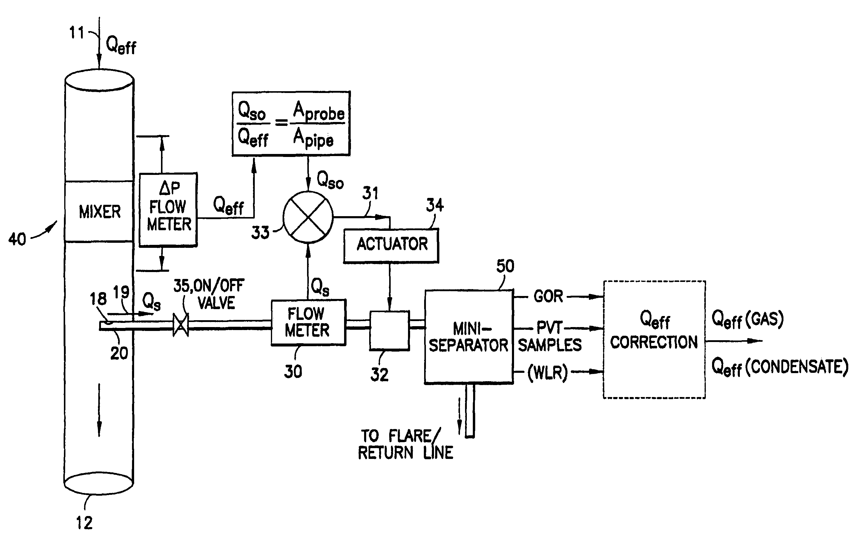
[0109]A portion of a fluid stream is sampled, and the flow rate QS of that sampled portion measured. The total flow rate Q of the fluid stream is also independently measured, and the ratio of the two measured flow rates calculated. Based on this ratio, the sampling flow rate (i.e. the proportion of the fluid stream which is sampled) is adjusted in order to substantially obtain isokinetic sampling conditions. This process is preferably either repeated or carried out continuously throughout the sampling process.

[0110]The sampled portion may be analysed concurrently with the flow rate measurements and adjustments, for example to provide the GOR, the WLR and samples for PVT analysis. This analysis may also use the flow rate measurement of the sampled portion.

[0111]FIG. 4 shows an isokinetic sampling system according to an embodiment of the present invention.

[0...


PUM

PropertyMeasurementUnit
energy mixture densityaaaaaaaaaa
diameteraaaaaaaaaa
diameteraaaaaaaaaa

Abstract

A method of sampling a multi-phase fluid stream is provided which comprises the steps of: sampling, with a sampling probe, a portion of the fluid stream; measuring the flow rate of said sampled portion; and measuring, independently of the sampling step, the total flow rate of the fluid stream, wherein the flow rate of the sampled portion is controlled according to the ratio of the flow rate of the sampled portion to the flow rate of the fluid stream, in order to obtain substantially isokinetic sampling of the fluid stream. The method may provide isokinetic sampling to an accuracy of 5% or less and preferably only samples a small portion of the fluid stream. The method has particular application for high rate condensate gas wells. A corresponding sampling system is provided which has particular application in the sampling of streams from well-heads. A flow conditioner for use with sampling methods and systems is also provided, the flow conditioner being a pipe section including: a swirl inducing section; a flow straightener; and an orifice plate.

Description

[0001]This application claims the benefits of priority from:[0002]i) Application Number 0322702.2, entitled “ISOKINETIC SAMPLING,” filed in the United Kingdom on 29 Sep. 2003; and[0003]ii) Application Number PCT / GB2004 / 003849, entitled “ISOKINETIC SAMPLING,” filed under the PCT on Sep. 9, 2004;[0004]All of which are commonly assigned to assignee of the present invention and hereby incorporated by reference in their entirety.BACKGROUND OF THE DISCLOSURE[0005]The present invention relates to isokinetic sampling. It is particularly, but not exclusively, related to methods and apparatuses for carrying out isokinetic sampling, and in particular isokinetic sampling in oilfield applications.[0006]In oilfield applications, as in many other fields, it is important to be able to analyse the composition and properties of a multi-phase fluid stream, such as a gas-condensate stream or a wet-gas stream. In particular it is desired to know the quantity of the various phases of the flow, for exampl...

Claims


Application Information

Patent Timeline
Patent Type & Authority Patents(United States)
IPC IPC(8): G01N1/20G01F1/34G01F1/74G01N1/22
CPCB01F5/0682B01F5/0688G01F1/34G01F1/42G01F1/44G01F5/00G01F25/003G01N1/2035G01N1/38G01F1/74G01N2001/225G01F25/13B01F25/45B01F25/4521G01N1/10B01F25/10B01F25/40
Inventor XIE, CHENG-GANGATKINSON, IANHAMMOND, PAULODDIE, GARYBOLCHOVER, PAUL
Owner SCHLUMBERGER TECH CORP
Why Eureka
Try Eureka