

System and method for cooling a combustion gas charge
a technology of combustion gas and cooling system, which is applied in the direction of mechanical equipment, machines/engines, and non-fuel substance addition to fuel, etc., can solve the problems of inability to cool compressed intake air or mix exhaust gas, exhaust gas having an unacceptable temperature,
- Summary
- Abstract
- Description
- Claims
- Application Information
AI Technical Summary
Benefits of technology
Problems solved by technology
Method used
Image

Examples
example 1
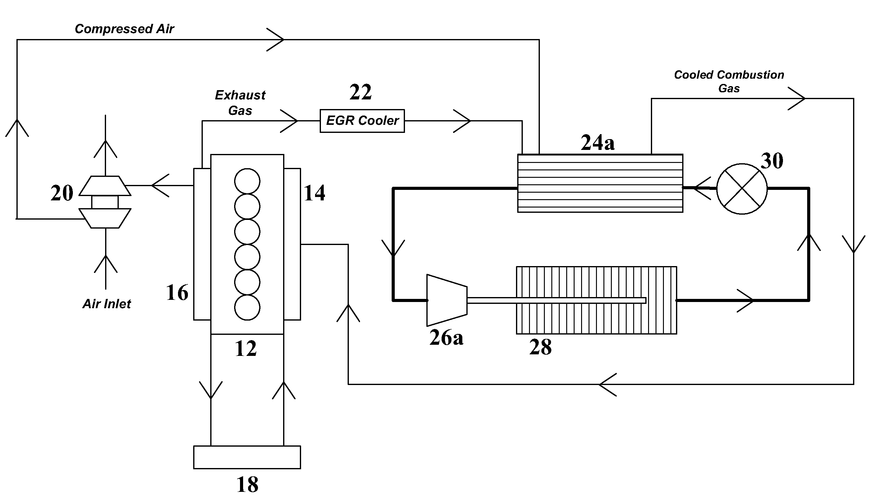
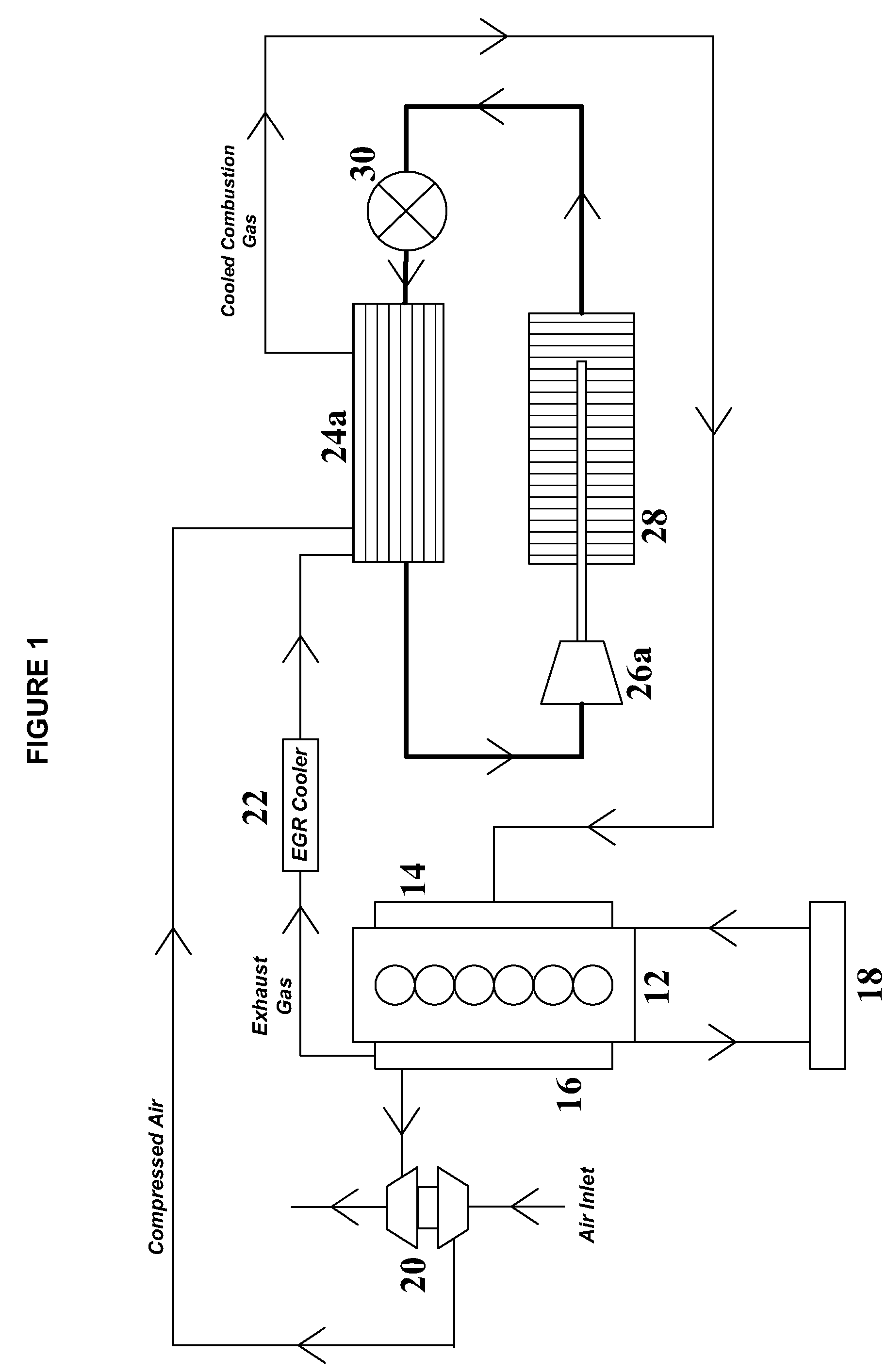
[0042]With respect to FIG. 1, an exemplary turbocharged diesel engine (e.g., engine 12) may produce about 468 horsepower (hp) at about 1740 revolutions per minute (rpm). The engine may have a compressed intake air flow rate of about 0.46 kg / s at a temperature of about 232° C. and a pressure of about 2.37 bar. The engine may have a recirculated exhaust gas flow rate of about 0.23 kg / s at a temperature of about 204° C. after passing through an exhaust gas recirculation cooler (e.g., exhaust gas recirculation cooler 22). When mixed, the net compressed intake air and precooled recirculated exhaust gas combustion charge may have a flow rate of about 0.693 kg / s and a temperature of 223° C.
[0043]To provide an acceptable intake combustion gas charge temperature of about 66° C., the mixed compressed intake air and recirculated exhaust gas may be cooled by about 114 kW of cooling. This cooling may be provided by passing the combined combustion gas charge through an evaporator (e.g., evaporato...
example 2
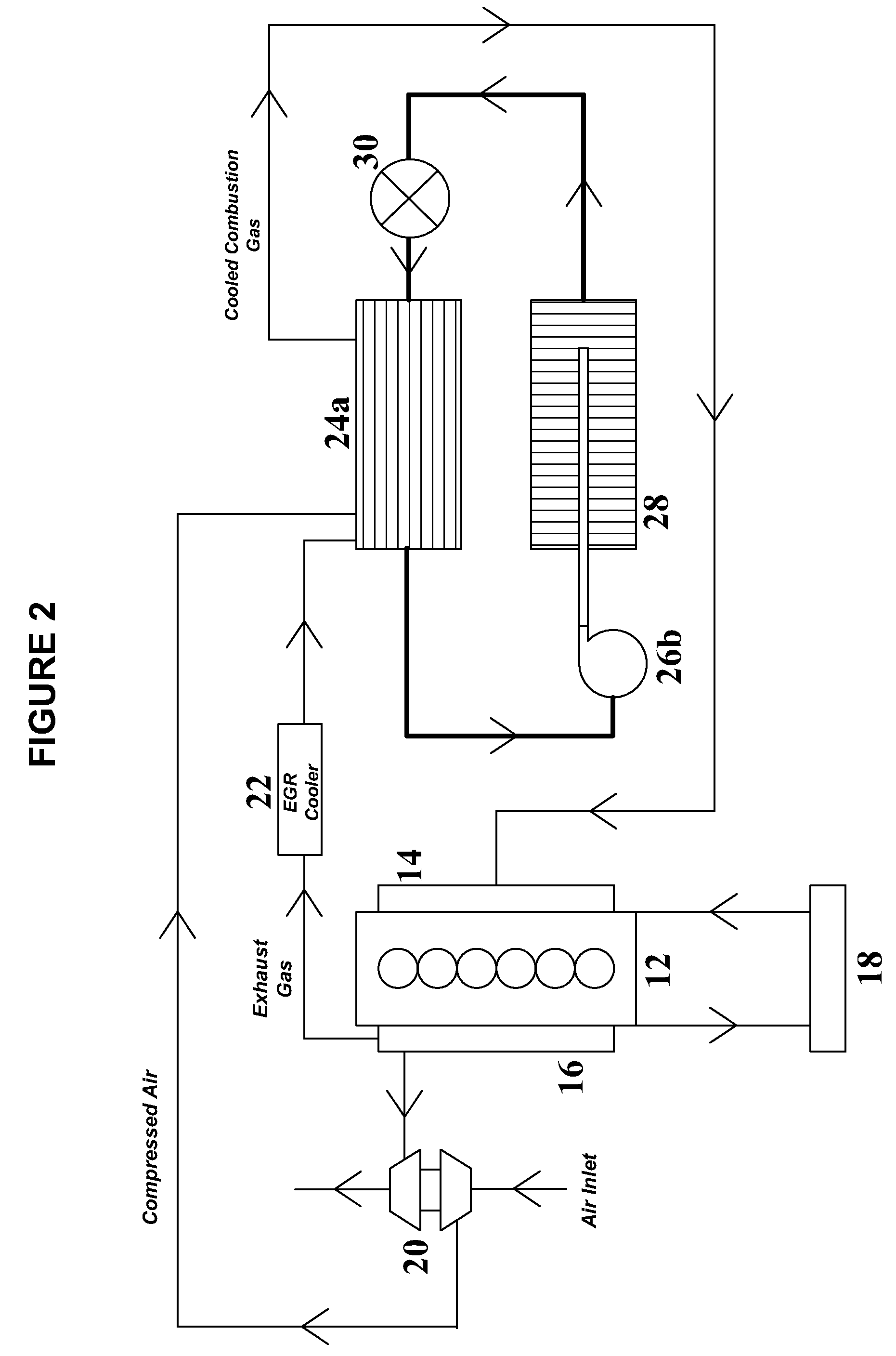
[0045]With respect to FIG. 2, an exemplary turbocharged diesel engine (e.g., engine 12) may produce about 468 horsepower (hp) at about 1740 revolutions per minute (rpm). The engine may have a compressed intake air flow rate of about 0.46 kg / s at a temperature of about 232° C. and a pressure of about 2.37 bar. The engine may have a recirculated exhaust gas flow rate of about 0.23 kg / s at a temperature of about 204° C. after passing through an exhaust gas recirculation cooler (e.g., exhaust gas recirculation cooler 22). When mixed, the net compressed intake air and precooled recirculated exhaust gas combustion charge may have a flow rate of about 0.693 kg / s and a temperature of 223° C.
[0046]To provide an acceptable intake combustion gas charge temperature of about 66° C., the mixed compressed intake air and recirculated exhaust gas may be cooled by about 114 kW of cooling. This cooling may be provided by passing the combined combustion gas charge through an evaporator (e.g., evaporato...
example 3
[0049]With respect to FIG. 3, an exemplary turbocharged diesel engine (e.g., engine 12) may produce about 468 horsepower (hp) at about 1740 revolutions per minute (rpm). The engine may discharge exhaust gas having a temperature of about 544° C., wherein the recirculated exhaust gas flow rate may be about 0.23 kg / s. Prior to mixing with compressed intake air in a gas mixer (e.g., gas mixer 32), the recirculated exhaust gas may be cooled to a temperature of about 204° C. The combined charge (i.e., compressed air and exhaust gas) may then be further cooled (e.g., in AA-CCC 34) to a temperature of about 66° C. before introduction to the intake manifold of an engine (e.g., intake manifold 14).
[0050]About 89 kW of cooling may be required to reduce the recirculated exhaust gas temperature from about 544° C. to about 204° C. This cooling may be provided by an agitated thin film evaporator (e.g., evaporator 24b) having a relatively low aqueous glycol solution flow rate of about 4.88 kg / s, wh...
PUM
 Abstract
Description
Claims
Application Information