
Polyaxial pedicle screw having a rotating locking element

a technology of locking element and screw, which is applied in the field of screw and coupling element assembly, can solve the problems of increasing operating time, limiting the range of motion, and affecting the operation of the patient,

Inactive Publication Date: 2010-05-25
K2M
View PDF22 Cites 65 Cited by
  • Summary
  • Abstract
  • Description
  • Claims
  • Application Information

AI Technical Summary

Benefits of technology

The assembly provides polyaxial freedom of implantation, reduces the number of elements required, simplifies the locking process, and ensures long-term fixation support, enhancing the reliability and durability of spinal alignment and stabilization.

Problems solved by technology

Genetic or developmental irregularities, trauma, chronic stress, tumors, and disease, however, can result in spinal pathologies which either limit this range of motion, or which threaten the critical elements of the nervous system housed within the spinal column.
It has been identified, however, that a considerable difficulty is associated with inserting screws along a misaligned curvature and simultaneously exactly positioning the coupling elements such that the rod receiving portions thereof are aligned so that the rod can be passed therethrough without distorting the screws.
Attempts at achieving proper alignment with fixed screws is understood to require increased operating time, which is known to enhance many complications associated with surgery.
Often surgical efforts with such fixed axes devices cannot be achieved, thereby rendering such instrumentation attempts entirely unsuccessful.
The art contains a variety of attempts at providing instrumentation which permit a limited freedom with respect to angulation of the screw and the coupling element These teachings, however, are generally complex, inadequately reliable, and lack long-term durability.
These considerable drawbacks associated with prior art systems also include difficulty in properly positioning the rod and coupling elements, and the tedious manipulation of the many parts that are used in the prior art to lock the rod, the screw, and the coupling element in position once they are properly positioned.
It is not unusual for displacement to occur as these parts are manipulated to lock the elements, which is clinically unacceptable, and repeated attempts at locking the elements in proper position must be made to remedy this displacement.

Method used


Image

  • Polyaxial pedicle screw having a rotating locking element
  • Polyaxial pedicle screw having a rotating locking element
  • Polyaxial pedicle screw having a rotating locking element

Examples


Embodiment Construction

[0037]While the invention will be described more fully hereinafter with reference to the accompanying drawings, in which particular embodiments and methods of implantation are shown, it is to be understood at the outset that persons skilled in the art may modify the invention herein described while achieving the functions and results of this invention. Accordingly, the descriptions which follow are to be understood as illustrative and exemplary of specific structures, aspects and features within the broad scope of the invention and not as limiting of such broad scope.

[0038]In an embodiment, the invention provides a screw and coupling element assembly for use with an orthopedic rod implantation apparatus. The assembly includes a securing element such as, for example, a screw, that has a head and a shaft that extends from the head. Other securing elements can include, for example, lamina hooks and sacral blocks.

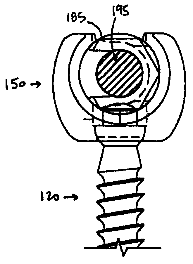
[0039]Accordingly, FIG. 4a illustrates a side view of a screw 120 suitable...


PUM


Abstract

A screw and coupling element assembly for use with an orthopedic rod implantation apparatus includes a screw with a head and a shaft extending from the head, a coupling element with a seat within which the head is seatable such that the shaft protrudes from the coupling element, and a locking element mateable with the coupling element and when mated is selectively movable through a plurality of positions including unlocked and locked positions. When in the unlocked position, the locking element presents a rod-receiving channel and the head is movable in the seat such that the shaft is directable in a plurality of angles relative to the coupling element. When in the locked position, a rod disposed within the rod-receiving channel is fixed relative to the coupling element and the head is immovable in the seat such that the shaft is fixed at an angle relative to the coupling element.

Description

CROSS REFERENCE TO RELATED APPLICATION[0001]This application is a continuation of U.S. patent application Ser. No. 10 / 115,747 entitled “Polyaxial Pedicle Screw Having a Rotating Locking Element”, filed Apr. 3, 2002, now U.S. Pat. No. 6,840,940 which is a continuation of U.S. patent application Ser. No. 09 / 789,935, filed Feb. 15, 2001, now U.S. Pat. No. 6,451,021. The entire contents of each of these prior applications are hereby expressly incorporated by reference.FIELD OF THE INVENTION[0002]The invention relates generally to screws and coupling element assemblies for use with orthopedic fixation systems. More particularly, the invention relates to a screw and coupling element assembly, for use with an orthopedic rod implantation apparatus, that includes a locking element that simultaneously locks a head of the screw within a seat of the coupling element so that a shaft of the screw is fixed at an angle relative to the coupling element and a rod, of the orthopedic rod implantation a...

Claims


Application Information

Patent Timeline
Patent Type & Authority Patents(United States)
IPC IPC(8): A61B17/70A61B17/86A61B17/88
CPCA61B17/7032A61B17/7037A61B17/7082A61B17/7091A61B17/7076A61B17/861
Inventor RALPH, JAMES D.TATAR, STEPHEN
Owner K2M
Learn More