Fluorescent lamp and manufacturing method thereof

a technology of fluorescent lamps and manufacturing methods, which is applied in the manufacture of electrode systems, discharge tubes with luminescent screens, discharge tubes, etc., can solve the problems of difficult to apply the technology disclosed in the patent to produce eefl, and the composition of metal oxides is not disclosed, so as to improve the lifetime and luminance of fluorescent lamps. , the effect of increasing the secondary electron emission ra

Inactive Publication Date: 2010-06-01
DMS CO LTD
View PDF26 Cites 0 Cited by
  • Summary
  • Abstract
  • Description
  • Claims
  • Application Information

AI Technical Summary

Benefits of technology

[0013]The present invention provides a fluorescent lamp having a metal oxide passivation layer that can prevent or suppress a darkening phenomenon and increase a secondary electron emission rate, thereby improving the lifetime and luminance of the fluorescent lamp.

Problems solved by technology

However, when the fluorescent lamp is used for a long time, a darkening phenomenon occurs by an amalgam generated from the reaction of mercury filled in the fluorescent lamp with an alkali component of a glass substrate, or by an impurity of the discharge gas released from impure trace residues of the fluorescent substance.
However, the patent 2001-0074017 only estimates the effect of using the metal oxide and does not prove the effect.
Furthermore, the patent does not disclose a composition of the metal oxide.
Moreover, a method for forming the ferroelectric layer is not provided.
Therefore, it is difficult to apply the technology disclosed in the patent to produce an EEFL having the cylindrical glass tube having a relatively small diameter.
Also, it is difficult to have a uniform passivation layer due to deterioration of colloid stability, which is caused by aggregation of the γ-Al2O3 particles.
However, when the glass tube is a capillary type, it is impossible to form the passivation layer on the capillary type glass tube for the fluorescent lamp.

Method used


Image

  • Fluorescent lamp and manufacturing method thereof
  • Fluorescent lamp and manufacturing method thereof
  • Fluorescent lamp and manufacturing method thereof

Examples


first embodiment

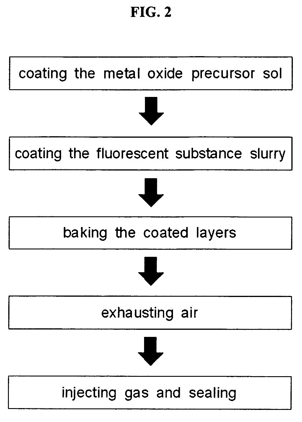
[0063]Referring FIG. 2, the dispersed metal oxide precursor is wet-coated on an entire surface of the inner wall of the glass tube of the EEFL (the first coating process), according to the present invention. Then, the fluorescent substance slurry is wet-coated on an entire surface of the dispersed metal oxide precursor, and passivation and fluorescent layers are formed simultaneously by baking the coated layers. Thereafter, the processes for exhausting the air from the inside of the glass tube, injecting the discharge gas, and sealing the glass tube are conducted, thereby completing the fluorescent lamp.

[0064]The coating of the dispersed metal oxide precursor and the fluorescent slurry may be conducted through dip coating, blade coating, slit coating, or spray coating.

[0065]FIG. 3 is a cross-sectional view of a fluorescent lamp according to a second embodiment of the present invention, and FIG. 4 is a flowchart illustrating a method of manufacturing the fluorescent lamp of FIG. 3. I...

third embodiment

[0069]FIG. 5 is a side sectional view of a fluorescent lamp according to the present invention, and FIG. 6 is a flowchart illustrating a method of manufacturing the fluorescent lamp of FIG. 5.

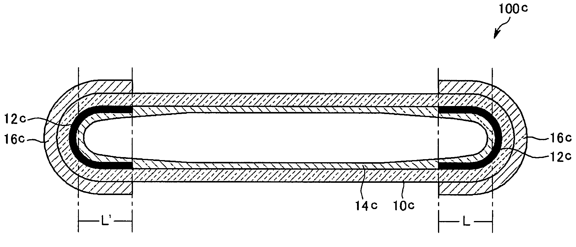
[0070]Referring to FIG. 5, an EEFL 100c of this third embodiment includes a passivation layer 12c on regions L and L′ of an inner wall of a glass tube 10c, which correspond to external electrodes 16c, and a fluorescent layer 14c is formed on an entire surface of the inner wall of the glass tube 10c covering the passivation layer 12c.

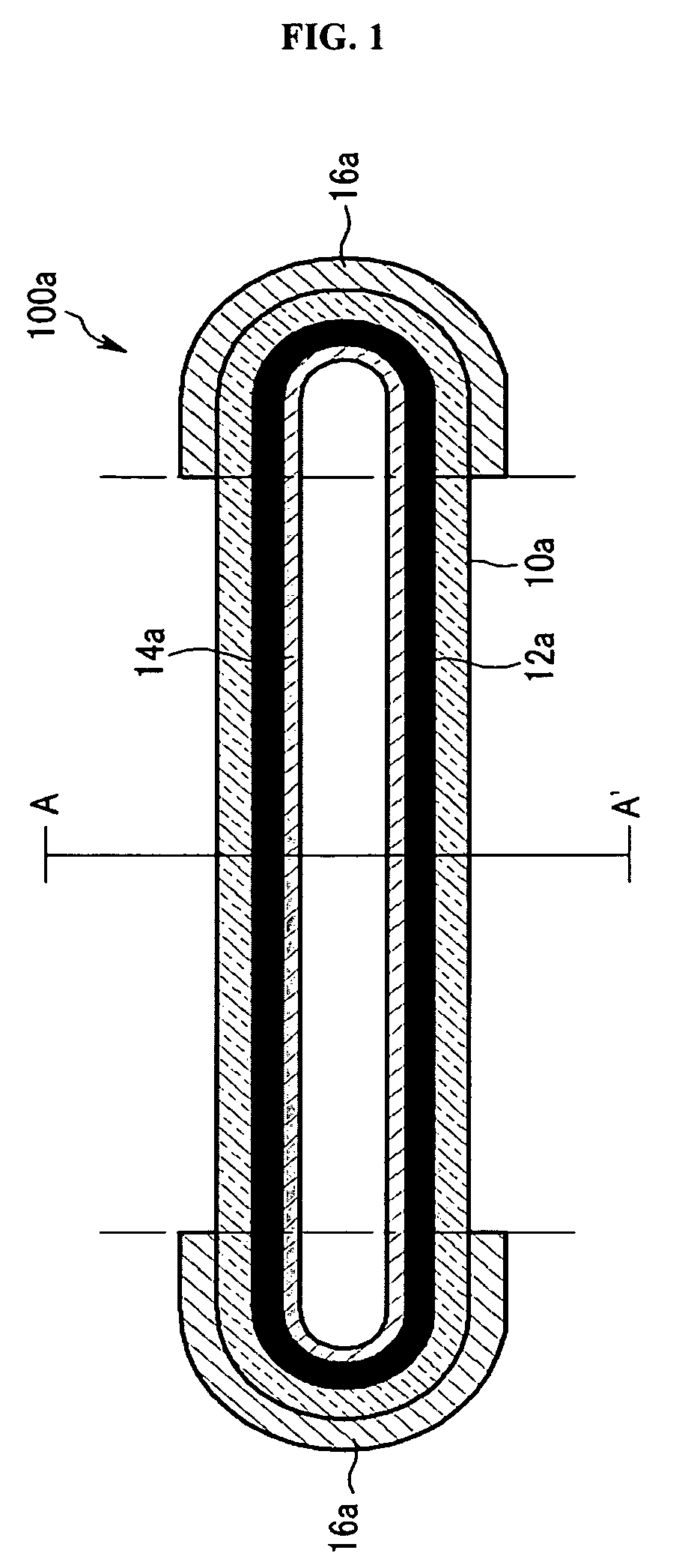
[0071]Since other components of the EEFL of this embodiment are identical to those of the fluorescent lamp of FIG. 1, the detailed description thereof will be omitted herein.

[0072]Referring to FIG. 6, in order to manufacture the EEFL of this embodiment, a metal oxide sol is coated on the regions L and L′ (the first coating process), and a fluorescent slurry is coated on the entire surface of the inner wall of the glass tube to cover the metal oxide sol coated on th...

fourth embodiment

[0073]FIG. 7 is a side sectional view of an EEFL according to the present invention.

[0074]Referring to FIG. 7, unlike the EEFL 10c of FIG. 3, in an EEFL 100d of this fourth embodiment of the present invention, a fluorescent layer 14d is formed on an entire surface of an inner wall of a glass tube 10d, and a passivation layer 12d is formed on regions L and L′ of the fluorescent layer 14d, which correspond to lengths of external electrodes 16d.

[0075]Since other components of the EEFL of this embodiment are identical to those of the fluorescent lamp of FIG. 1, the detailed description thereof will be omitted herein.

[0076]Referring to FIG. 8, in order to manufacture the fluorescent lamp of this embodiment, a fluorescent slurry is first coated on the entire surface of the inner wall of the glass tube (the first coating process). Then, a metal oxide sol is coated on the regions L and L′ of the fluorescent slurry coated on the entire surface of the inner wall of the glass tube (the second...


PUM

PropertyMeasurementUnit
temperatureaaaaaaaaaa
particle sizeaaaaaaaaaa
thicknessaaaaaaaaaa

Abstract

A method of manufacturing a fluorescent lamp is provided. One of a dispersed metal oxide precursor sol prepared by a sol-gel reaction and a fluorescent substance slurry is coated on a glass tube having at least one open side and then the other of the fluorescent substance slurry and the dispersed metal oxide precursor sol is coated on the glass tube. Next, passivation and fluorescent layers are simultaneously formed by baking the coated layers. Then, air is exhausted out of the glass tube and a discharge gas is injected into the glass tube. Finally, the glass tube is sealed.

Description

CROSS REFERENCE TO RELATED APPLICATION[0001]This application claims priority to and the benefit of Korean Application No. 10-2005-0129678 filed in the Korean Patent Office on Dec. 26, 2005, the entire content of which is incorporated herein by reference.FIELD OF THE INVENTION[0002]The present invention relates to a fluorescent lamp and a manufacturing method thereof, and more particularly, to a fluorescent lamp having a uniform passivation layer that can prevent or suppress a darkening phenomenon occurring when driving the fluorescent lamp and can increase a secondary electron emitting rate, thereby improving the lifetime and luminance of the fluorescent lamp, and a method of manufacturing the fluorescent lamp.BACKGROUND OF THE INVENTION[0003]Fluorescent lamps are classified into a cold cathode fluorescent lamp (CCFL) having electrodes disposed inside of a cylindrical glass tube and an external electrode fluorescent lamp (EEFL) having electrodes disposed outside of the glass tube.[0...

Claims


Application Information

Patent Timeline
Patent Type & Authority Patents(United States)
IPC IPC(8): H01J9/00
CPCH01J9/223H01J61/35H01J61/302H01J61/38
Inventor PARK, YONG-SEOK
Owner DMS CO LTD
Why Eureka
Try Eureka