
Air intake noise reducing device, internal combustion engine fitted with the same and structure for fitting the same to the internal combustion engine

a technology of air intake and noise reduction device, which is applied in the direction of intake silencers for fuel, combustion air/fuel air treatment, machines/engines, etc., can solve the problem of large amount of air being sucked, and achieve the effect of less assembly man-hours and reduced air intake noises in internal combustion engines

Active Publication Date: 2010-06-08
KOKOKU INTECH CO LTD
View PDF33 Cites 15 Cited by
  • Summary
  • Abstract
  • Description
  • Claims
  • Application Information

AI Technical Summary

Benefits of technology

[0025]The present invention can provide the air intake noise reducing device with less assembling man-hours as maintaining the sealing property. The present invention can also provide internal combustion engines fitted with such devices and the structure for fitting such device to the internal combustion engine, so that air intake noises generated in the internal combustion engines are reduced.

Problems solved by technology

When the throttle valves are opened rapidly, large amount of air is sucked in a short period, so that unusual sounds or noises are caused in surge tanks, intake manifolds and the like connected to or arranged at downstream of the throttle valves.

Method used


Image

  • Air intake noise reducing device, internal combustion engine fitted with the same and structure for fitting the same to the internal combustion engine
  • Air intake noise reducing device, internal combustion engine fitted with the same and structure for fitting the same to the internal combustion engine
  • Air intake noise reducing device, internal combustion engine fitted with the same and structure for fitting the same to the internal combustion engine

Examples


embodiment 1

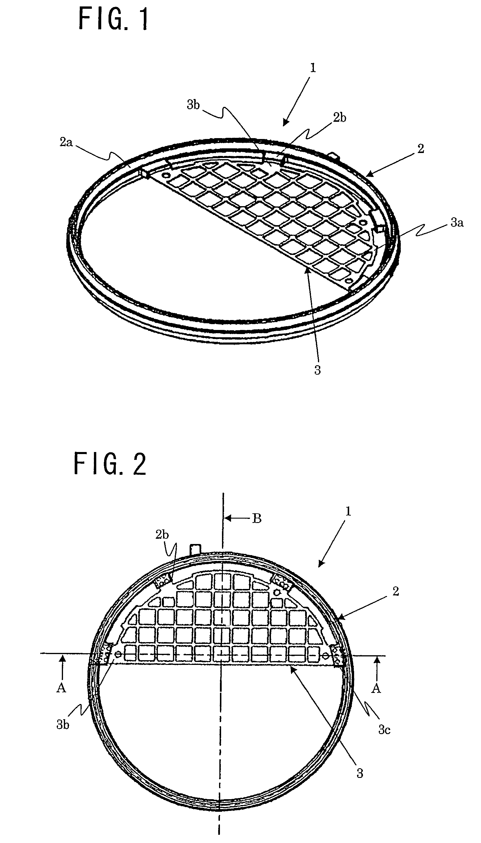
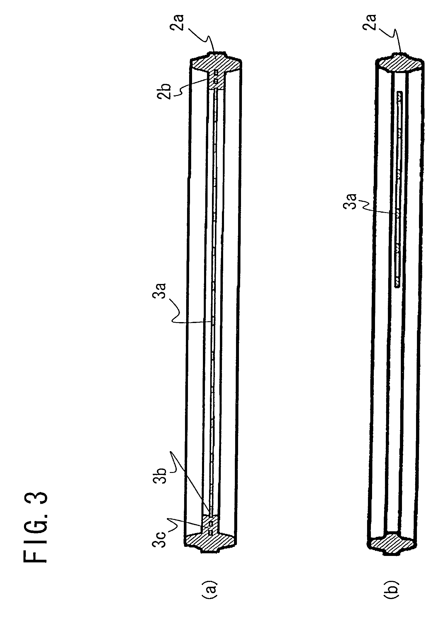
[0036]FIG. 1 is the perspective schematic view illustrating the whole structure of embodiment 1. An air intake noise reducing device 1 has a gasket 2 functioning as a seal member and a net member 3 functioning as an air intake noise reducing member arranged inside the gasket 2. In the present embodiment, the gasket 2 is made of the same rubber as that employed by the conventional air intake noise reducing device, and the net member 3 is made of the same metal as that also employed by the conventional air intake noise reducing device. But materials for the gasket or the net member are not limited to the same rubber or the same metal as the conventional device.

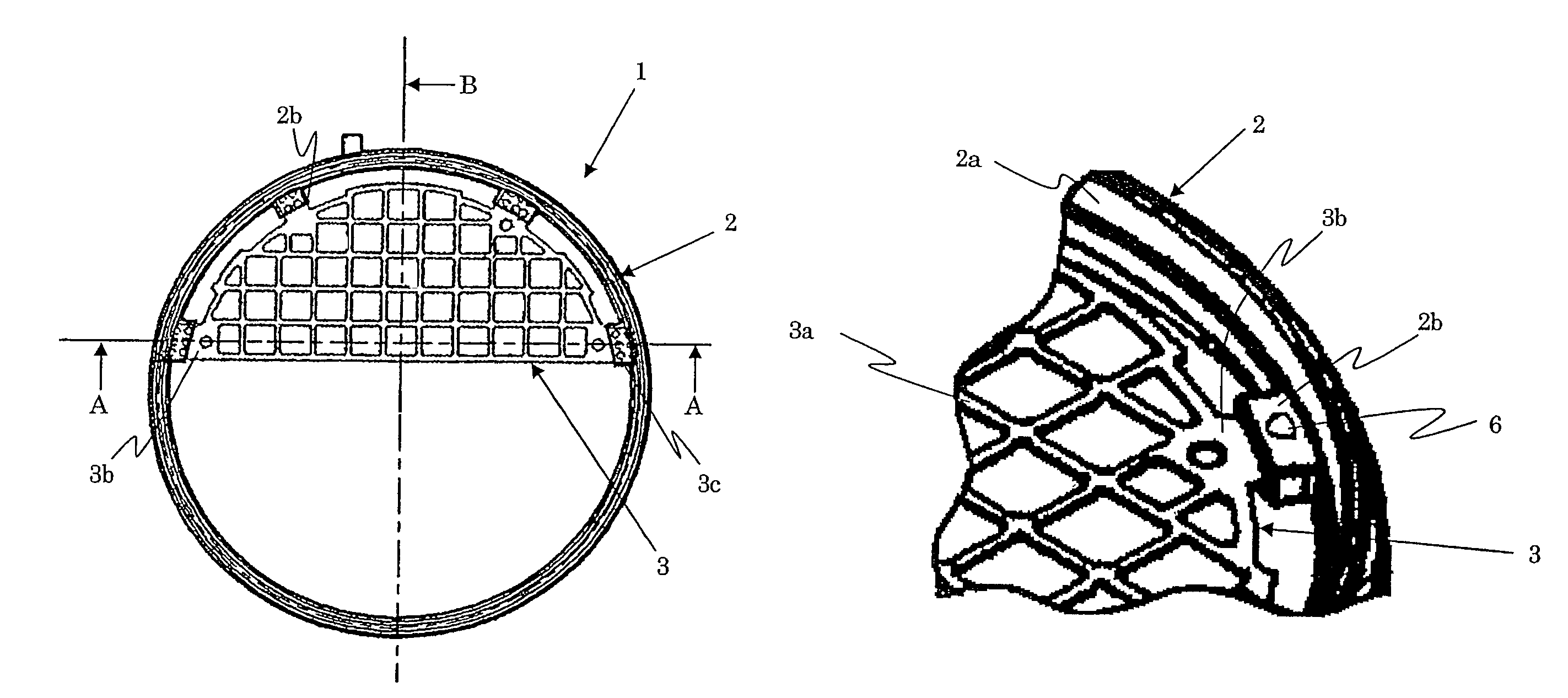
[0037]The gasket 2 has a ring member 2a which is held by the both ends of the pipe members of the air intake passage 100 as illustrated in FIG. 6. Protrusion holding portions 2b are formed on an inside surface of the ring member 2a as extending toward the center of the gasket 2.

[0038]The net member 3 has a net 3a which covers a ...

embodiment 2

[0050]The present embodiment relates to an internal combustion engine where the air intake noise reducing device 1 by embodiment 1 is arranged in the air intake passage 100. Therefore, only features different from embodiment 1 are explained and the same reference numerals or characters are assigned to the same components.

[0051]FIG. 4 is the perspective view illustrating the air intake noise reducing device by embodiment 2 attached to the connecting portion of the air intake passage.

[0052]A seal holding groove 4 for holding the ring member 2a of the gasket 2 is formed in the connecting portion of the air intake passage 100. Protrusion holding recesses 5 for holding the protrusion holding portions 2b of the gasket 2 are formed inside the seal holding groove 4.

[0053]When the air intake noise reducing device 1 is attached to the air intake passage 100 via the connecting portion of the air intake passage 100, the ring member 2a of the gasket 2 is held in the seal holding groove 4. And th...

embodiment 3

[0055]In the present embodiment, a concave member for positioning is formed on a surface of the protrusion holding portion 2b of the air intake noise reducing device 1 by embodiment 1. Therefore, only features different from embodiments 1 and 2 are explained and the same reference numerals or characters are assigned to the same components.

[0056]FIG. 5 is the partial perspective view illustrating the characteristic portion of the present embodiment.

[0057]In FIG. 5, a reference numeral 6 is a concave portion for positioning. The concave portion 6 for positioning is formed on both sides of the protrusion holding portion 2b, namely upstream and downstream sides of the air intake noise reducing device.

[0058]When the air intake noise reducing device 1 is attached to the air intake passage 100, the protrusion holding portions 2b are held in the protrusion holding recesses 5. And the air intake passages 100 are connected on both sides of the air intake noise reducing device, the concave por...


PUM


Abstract

The present invention provides an air intake noise reducing device, an internal combustion engine fitted with the air intake noise reducing device and a structure for fitting the air intake noise reducing device to the internal combustion engine. The air intake noise reducing device comprises a gasket (2) comprising a ring member (2a) held by connecting surfaces of an air intake passage (100) and protrusion holding portions (2b) extending from the ring member (2a) toward a center of the air intake passage (100); and a net member (3) comprising a net (3a) for rectifying intake air and connecting protrusions (3b) extending outward from the net (3). The connecting protrusions (3b) are held in the protruding holding portions (2b) such that the ring member (3) is firmly secured to the gasket (3). The air intake noise reducing device constituted by in the above-mentioned manner can reduce assembly man-hours without deteriorating a sealing property of the air passage.

Description

[0001]This application claims the benefit of Japanese Application No. 2006-072447 filed Mar. 16, 2006 and PCT / JP2007 / 054944 filed Mar. 13, 2007, which are hereby incorporated by reference in their entirety.FIELD OF THE INVENTION[0002]The present invention relates to an air intake noise reduction device, an internal combustion engine fitted with the air intake noise reduction device and a structure for fitting the air intake noise reducing device to the internal combustion engine.RELATED BACKGROUND ART[0003]Conventionally, the amount of intake air to an internal combustion engine such as an automobile engine is adjusted by opening or closing throttle valves arranged in air intake passages. When the throttle valves are opened rapidly, large amount of air is sucked in a short period, so that unusual sounds or noises are caused in surge tanks, intake manifolds and the like connected to or arranged at downstream of the throttle valves.[0004]In order to suppress such unusual sounds, a str...

Claims


Application Information

Patent Timeline
Patent Type & Authority Patents(United States)
IPC IPC(8): F01N1/08F02M35/12F01N1/00F02M29/04F02M35/10
CPCF02M35/1216F02M35/1211F02M29/04F02D9/104
Inventor ASADA, SADAOFUNATSU, TAKUYAYAMASHITA, KENJI
Owner KOKOKU INTECH CO LTD
Learn More