Impedance control in connector mounting areas

a technology of impedance control and connector, which is applied in the direction of coupling device connection, coupling protective earth/shielding arrangement, electrical equipment, etc., can solve the problems of affecting the affecting the signal integrity of the entire signal transmission system, and adding significant cost to the connector, so as to reduce crosstalk

Active Publication Date: 2010-06-08
MOLEX INC
View PDF56 Cites 131 Cited by
  • Summary
  • Abstract
  • Description
  • Claims
  • Application Information

AI Technical Summary

Benefits of technology

[0008]It is therefore a general object of the present invention to provide an improved connector for high speed data transmission which has reduced crosstalk and which does not require large metal shields.
[0013]Yet a still further object of the present invention is to provide a high speed connector for use in backplane applications in which conductive terminals are mounted in a pair of terminal columns within a support frame, and wherein portions of the support frame are molded over the terminals to hold them in place, the ground shield terminal having windows portions cut out of their body portions in locations where the ground shield terminals cross a support frame member, and the signal terminals being narrowed in the area of the ground shield terminal windows, so as to increase their edge-to-edge spacing and maintain a desired coupling level between the signal terminal pair through the mounting area.
[0018]The radial spokes are continued on the interior surface of one of the connector unit wafer halves and serves as stand-offs to separate the columns of terminals when the two connector unit wafer halves are married together so that an air spacing is present between the columns of terminals. The signal and larger ground shield terminals make at least two bends in their extent through the connector body and in these bend areas, the impedance of the connector units is controlled by reducing the amount of metal present in both the differential signal terminal pair and in their associated ground shield terminals. This reduction is accomplished in the ground shield terminals by forming a large window therein and in the signal terminal by “necking” or narrowing the signal terminal body portions down in order to increase the distance between the signal terminal edges.

Problems solved by technology

As signal terminal are positioned closer together, signal interference occurs between closely spaced signal terminals especially between pairs of adjacent differential signal terminals.
This affects signal integrity of the entire signal transmission system.
These shields add significant cost to the connector and also increase the size of the connector.
However, the use of ground terminals the same size as the signal terminals leads to problems in coupling which may drive up the system impedance.
It becomes difficult to match the impedance within the body of the connector and along the body portions of the terminals in that the terminal body portions have different configurations and spacing than do the contact portions of the terminals.
This difficulty increases especially in areas of the connector where the terminals are mounted to their insulative support frames or housings.

Method used


Image

  • Impedance control in connector mounting areas
  • Impedance control in connector mounting areas
  • Impedance control in connector mounting areas

Examples


Embodiment Construction

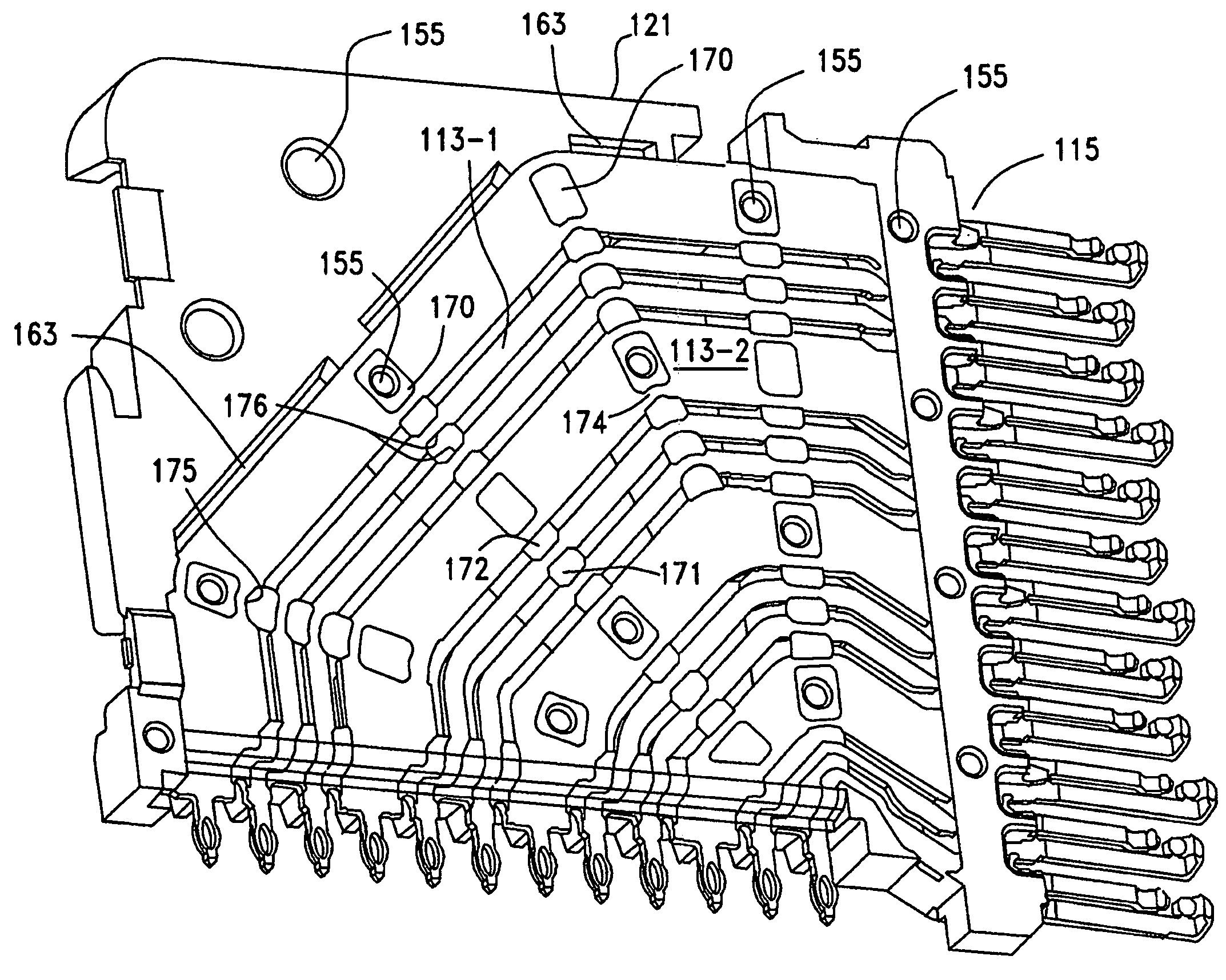
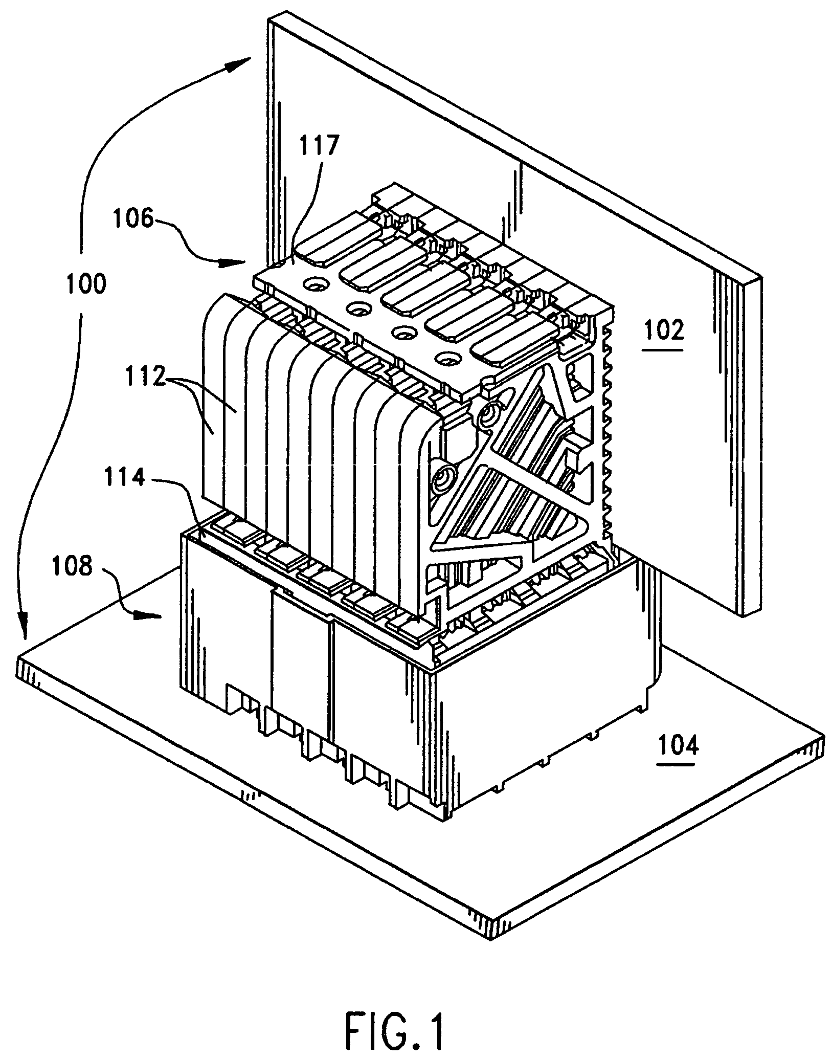
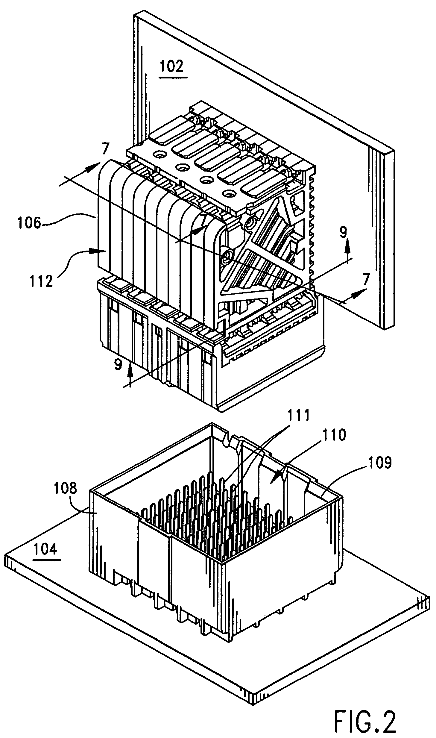
[0049]FIG. 1 illustrates a backplane connector assembly 100 that is constructed in accordance with the principles of the present invention and which is used to join an auxiliary circuit board 102, known in the art as a daughter card, to another circuit board 104, typically referred to in the art as a backplane. The assembly 100 includes two connectors 106 and 108. As shown best in FIG. 2, the backplane connector 108 takes the form of a pin header having an four sidewalls 109 that cooperatively define a hollow receptacle 110. A plurality of conductive terminals in the form of pins 111 are provided and held in corresponding terminal-receiving cavities of the connector 108 (not shown). The pins 111 are terminated, such as by tail portions to conductive traces on the backplane 104 and these tail portions fit into plated vias, or through holes disposed in the backplane.

[0050]Turning to FIG. 3, the daughter card connector 106 is composed of a plurality of discrete connector units 112 that...


PUM


Abstract

A high speed connector with reduced crosstalk utilizes individual connector support frames that are assembled together to form a block of connector units. Each such unit supports a column of conductive terminals in two spaced-apart columns. The columns have differential signal terminal pairs separated from each other by larger intervening ground shields that serve as ground terminals. The ground shields are arranged in alternating fashion within the pair of columns and they are closely spaced together so as to face a differential signal terminal pair. In areas where the terminals are mounted to the connector units, window-like openings are formed in the large ground shield terminals to reduce the amount of broadside coupling between the differential signal terminal pair and the signal terminal pair are narrowed to increase their edge-to-edge distance to account for the change in dielectric constant of the connector unit material filing in the area between the signal terminal pair.

Description

REFERENCE TO RELATED APPLICATIONS[0001]This application claims the domestic benefit of U.S. Provisional Application Ser. No. 60 / 936,385, filed on Jun. 20, 2007, which disclosure is hereby incorporated by reference.BACKGROUND OF THE INVENTION[0002]The present invention relates generally to high speed connectors, and more particularly to high speed backplane connectors, with reduced crosstalk and improved performance.[0003]High speed connectors are used in many data transmission applications particularly in the telecommunications industry. Signal integrity is an important concern in the area of high speed and data transmission for components need to reliably transmit data signals. The high speed data transmission market has also been driving toward reduced size components.[0004]High speed data transmission is utilized in telecommunications to transmit data received from a data storage reservoir or a component transmitter and such transmission most commonly occurs in routers and server...

Claims


Application Information

Patent Timeline
Patent Type & Authority Patents(United States)
IPC IPC(8): H01R13/648
CPCH01R13/514H01R13/6471H01R13/6585H01R13/65807H01R12/724H01R13/6477
Inventor AMLESHI, PEEROUZLAURX, JOHN
Owner MOLEX INC
Why Eureka
Try Eureka